A few infrastructure projects have happened in the last two years and I’ve been putting my efforts into youtube. I have more control on YouTube for creating content, and video has come along way since I started this blog. My iPhone 15 pro, a handheld gimbal, and tiny wireless microphones make video much easier to do now than in 2010. It also helps that 4K is now a breeze to edit and this blog service requires me to pay to upgrade features while YouTube pays me to make content via advertising revenue.
But I still enjoy writing and the timelessness of photos.
November 2022
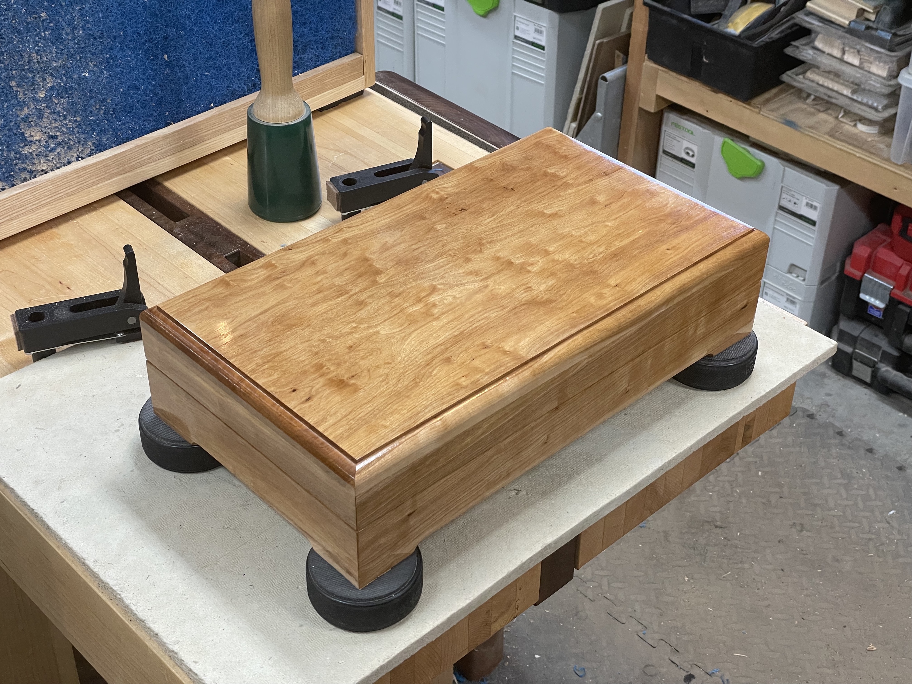
The first big project to update on is in the basement. The structural beam supporting the upstairs floor is nice… but could look better. I’ve had materials and a woodshed capable of producing something more polished but have had other priorities and never quite found the best way to make a more attractive beam. Then I found some time and learned about a joint called a miter-lock. To get some experience with the joinery needed I first made a ‘rock box’ for my daughter. She appreciated having a place to store her rock collection and I figured out the finer details of using a miter-lock joint.
The Beam was quite a process to assemble. Clamping and glueing up a long miter joint is made a bit easier with the interlocking joinery, but the clock is ticking once glue is added, and everything has to be perfect to get a gapless clean joint. The entire project is summarized in the following video. I really like how it turned out and now we are starting to look at solutions for putting up some sort of ceiling system in the finished part of the basement. I’d love to find some old metal ceiling tiles with a patina earned over several decades to install.
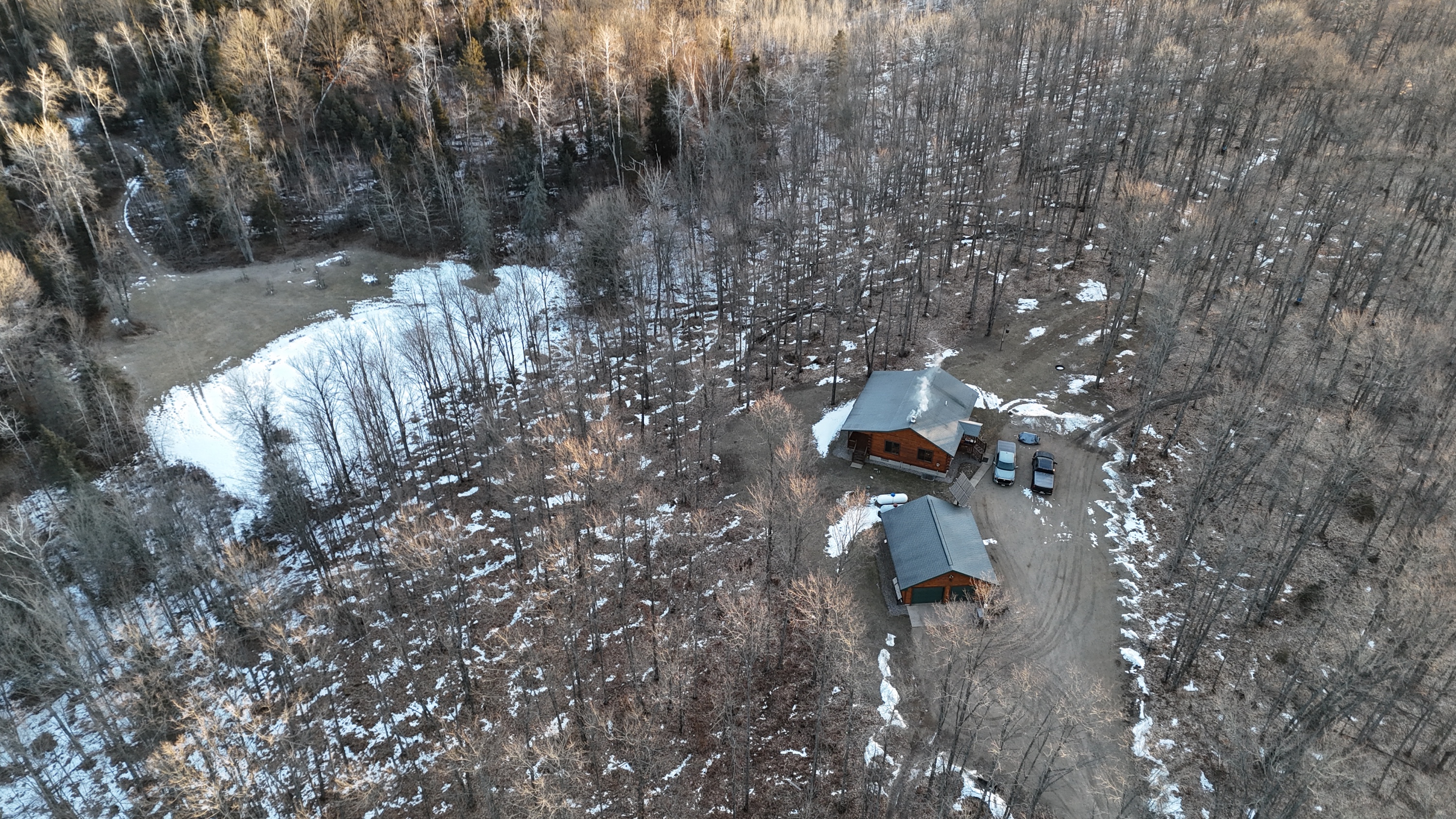
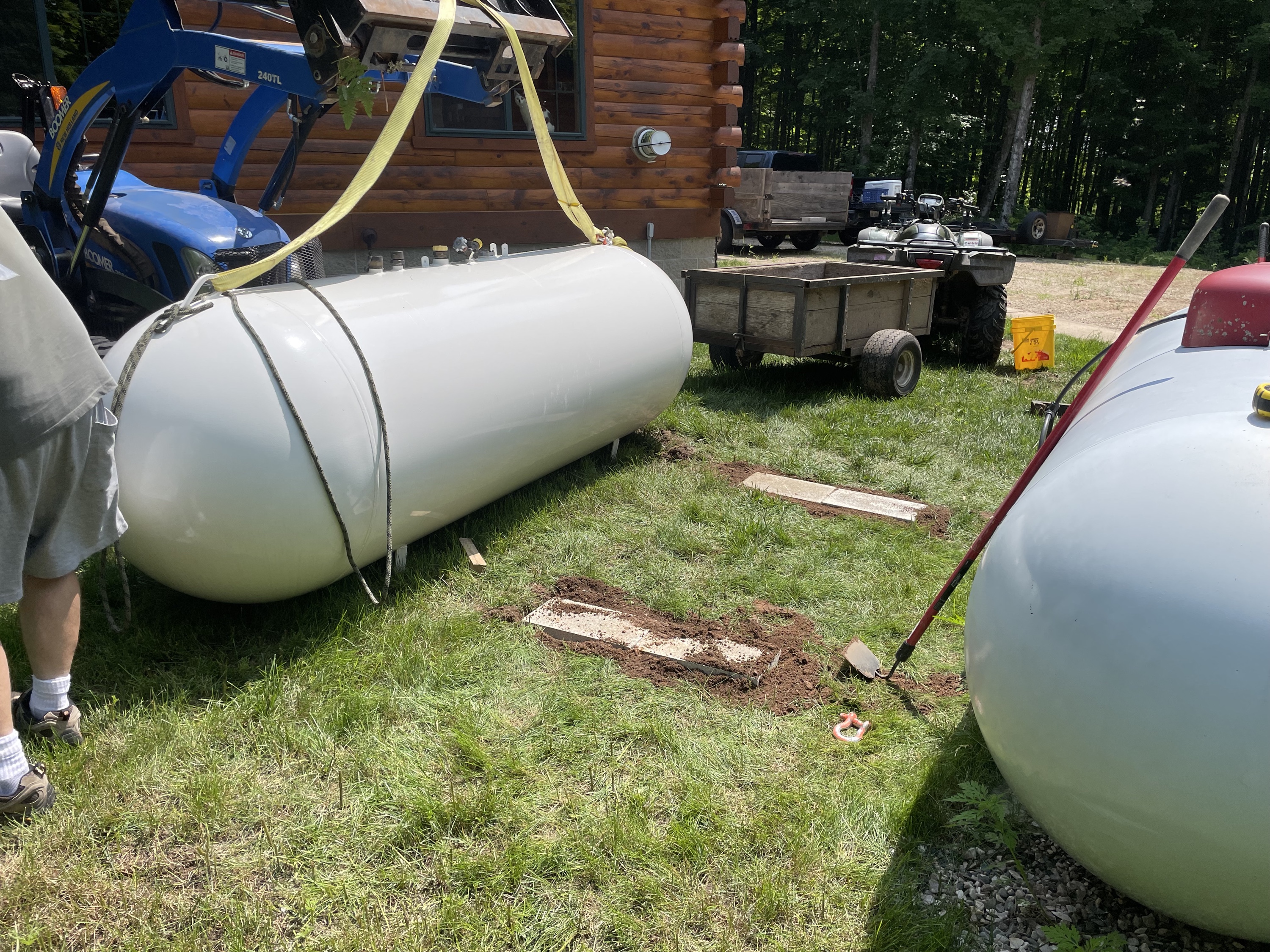
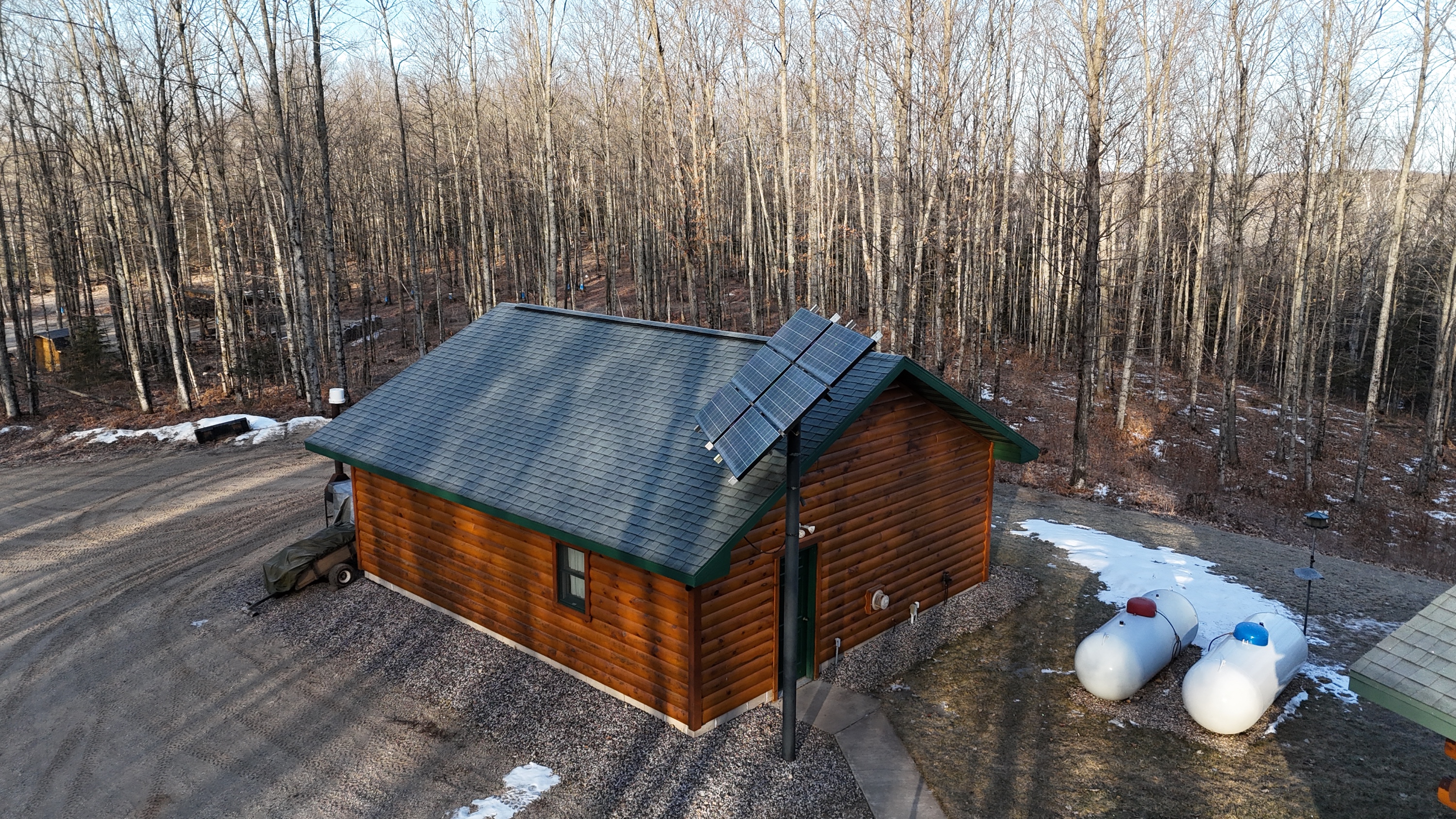
With the basement getting more use we then looked to solutions to make sure it is nice and warm and cozy in winter. We have heat and a propane tank… but two tanks is better than one.
6.22.2023 – Thursday
Propane tanks are notoriously hard to purchase in my area. We ended up finding a place that refurbishes tanks in Southern Wisconsin. The Ol’man brought a trailer and we moved that tank a few hundred miles back to camp. Turns out energy is often about control. If the company that sells the propane owns the tank they have more control over the price and when they fill it. Propane companies love to fill tanks when the price is high (winter) and spend summer charging customers to swap tanks when they aren’t selling as much fuel. Not a great way for an off-grid cabin to operate. This is further complicated by limited accessibility to large vehicles in winter.
The math is a bit fuzzy, but based on the 500 gallon tank I purchased for my house several years ago ($1100), it has paid for itself already. Now I come out ahead. I save $0.10 per gallon by owning a tank, fill up once a year when the cost is lowest (May-July) and don’t have to pay a surcharge to rent a tank (because I use less than 500 gallons a year). Each year I save about $150. A refurbished tank is about $2000 right now. Refurbished tanks are identical to a new tank but often have more steel in them and weight a bit more. They are stripped, powder coated (that is the good paint), and get all new fittings.
The cabin is kept at a base temperature around 45°F and when occupied we use wood for heat and propane for hot water. Each year we use about 350-400 gallons… so why two tanks?
A 500 gallon tank can only hold 400 gallons – there needs to be space for expansion and contraction of the propane. With temperature swings from 100°F to -10°F possible it’s best to stay under 80% max. If we get an unusually cold winter or can’t make as many nights as we’d like in a winter we risk running out, or paying for an expensive winter fill up. Plus, a lot of places will not fill a tank unless you need at least 200 gallons.
default
Now we make one call and fill up once a year, always maintaining a comfortable reserve.
If you are unfamiliar with two propane tanks work together and how the heck they both empty at the same time… well, they don’t. Each tank is high pressure (100-200 psi). It drops from high pressure to about 10-12 psi at the regulator on the top of the tank. In theory, if the tanks are set to exactly the same at each regulator (say 11.55 psi) they would empty at the same rate. That never happens though, so one will empty first, then the next one will empty. Because gas flows from high to low pressure one tank cannot fill the other. The next regulator on the cabin drops 10-12 psi to less than 0.5 psi for appliances.
This year I took over the boil and it was a data driven season. I began work in July 2021 when I designed and ordered parts for a home-built reverse osmosis sap concentration system (RO). The design was based heavily off of the work Dan Roseum did to make his RO. Check it out on his website – his diagrams explain the layout of components nicely. From this starting point I learned about the recirculation valve and incorporated it into my design – this little valve loops a portion of the concentrated sap back through the system to further concentrate it. My boil rate was too fast this year for me to take full advantage of the recirculate, but next year it will come into play when I upgrade from 3 membranes to five membranes.
RO is basically a membrane and a pressure pump. Water is a small molecule that can pass through a membrane with a bit of encouragement (high pressure). Sugar is a large molecule that does not pass through the membrane. Most of the sugars get washed off the membrane and into the preheater pan of the cooker, but after some of the sugar molecules load up on the membrane, the flow slows down. Then the RO needs to be flushed with water to wash the clogged membrane. A flush is usually 15-20 minutes.
I ran a test early in the development. A lot of things went wrong. I had leaks everywhere. Turns out pipe dope doesn’t cut it on these tiny high pressure plastic fittings. I redid everything with teflon tape and pressure checked to 150 PSI. This time everything worked perfectly. Lesson learned.
Next I spent a lot of time with a spreadsheet and worked on the math side of things. This is the data from running room temperature water through the RO, and it looked very promising.
Skip ahead to the end of season and my real world numbers were quite a bit different. Output was about 42% that of my room temperature water test and pressure was running about 45 PSI higher. I redid the spreadsheet with actual numbers from processing cold sap
Here is the video where I am optimistic that the RO will work like a champ… but unsure just how well things will go with cold sap.
With regards to the RO system I built I also have a complete parts list. Keep in mind I’m not including a few random fasteners (nuts and bolts) or the wood used. Keep reading to the very end of this post to see what updates are being done to the RO for next season. This parts list is complete and includes all the updated parts in the current to-this-day RO setup (the 2023 model).
I think I spent 20 hours on the initial research, development, and testing of the RO. If I traded my time for money this would be a very costly project, but I enjoy learning and see my 20 hours as an investment in understanding a new topic that I had no previous knowledge of before – and that is really exciting!
Maple Syrup 2022 – Batch #1
The Ol’man placed taps on March 18, 2022 and it was a slow start. We were originally delayed by an ice storm on our original tapping date March 11, 2022. Ultimately, it made no difference since the sap didn’t start running until after the taps were placed anyway.
The first collection ran from march 18 to March 31 and saw 285 gallons collected for the boil. I arrived after work on April 1, 2022 and set up, filling my pans with concentrate from the RO and setting my alarm for an early start. The following day I boiled all day, encountered a hardware problem, and limped to the finish line of batch #1on the morning of April 3, 2022.
The stats below reflect the summary of nearly 200 lines of data collected over the course of the boil… I was by myself for quite a while. I needed something to do. Pump 1 is the high output TYP 8900K model that I burned up the transformer for (7A pump with a 5A transformer). Pump 2 is the smaller Aquatech 8800 I originally purchased and kept for a spare. The final Brix is also the last reading, the boil continued for 2-4 minutes after and at the rate it was progressing should have put the finished syrup at 59°Bx at 210°F for pour off.
Boil time
18h
Wood used
1 face cord
Gallons sap
285 gal
Gallons Syrup
6 gal
Brix sap (hygrometer)
2.15%
Brix sap (actual)
2.1%
RO run time pump 1
12h
RO permeate p1 GPH
7.95
RO water removed p1 (gal)
95.44
RO run time pump 2
8h 13m 48s
RO permeate p2 GPH
5.49
RO water removed p2 (gal)
45.14
Total RO water removed (gal)
140.59
Water removed from boil (gal)
138.41
Brix final (@ 218°F)
57
Boil rate (GPH)
7.69
Taps
107
Sap Collection Days
13
The tricky part was knowing when to quench the fire and pull off the syrup. It basically just comes down to knowing the equipment – and that is where data collection proves its value. I was able to watch how fast the Brix was increasing over time and carefully watch my rate of boil to hit just the right timing.
Sarah and I were pouring off the finished syrup just as my folks arrived for the day. After the snow from the day before, it was nice to see some sun and relax a bit. But before heading out, the Ol’man and I collected more, and we started storing up sap for the next boil.
Maple Syrup 2022 – Batch #2
I returned on April 10, 2022 to the cabin after work. The Ol’man was there and staged some wood and set up the preheater pan. I got right to it, starting a fire and the RO before even thinking about getting supper. The jump start was well worth it. The next day I was able to shut down at sunset and get to bed early (compared to 12:30am the last time on batch #1).
The boil this time around was impressive. I set up an experimental sap preheater and it added 12-14°F to the sap. The RO worked flawlessly with its new 10A transformer. The woodburner was dialed in; the boil was so easy to modulate with the variable speed 12V inline blower fan. During peak efficiency I could move 10 GPH of water with the RO and boil off another 10 GPH while going 50+ minutes between loading the firebox with wood. The boil rate on the final day did slow way down, pulling the average down quite a bit, but the overall boil rate was still one for the record books despite the slowdown during the final 90 minutes of finishing.
Boil time
17h 36m 53s
Wood used
0.75 face cord
Gallons sap
335
Gallons Syrup
9.5
Brix sap (hygrometer)
3.09
Brix sap (calculated after boil)
2.47
RO run time pump
18h 9m 56s
RO permeate GPH
9.72
RO water removed (gal)
177
RO concentrate GPH
8.72
RO concentrate produced (gal)
158.37
Water removed from boil (gal)
149
Brix final (@ 218°F)
58.5
Boil rate (GPH)
8.5
RO preheater
12-14°F
Taps
107
Collection Days
10
I made another video and without having to worry about the RO performance was able to focus on optimizing the whole system.
It was great fun! I even celebrated with some maple root beer and rum.
This year’s syrup looks very good. It’s nice and light, whereas previous years it has been darker from the longer, slower, boil.
The Updated RO for 2023
The RO gets a few changes for 2023 (next year). I placed an order for two more membranes and there is a 2 month backorder on them. This is sort of the way things are now – as soon as the idea forms, make a plan, and then place an order so it is on hand when its needed in the future.
A bunch of little updates happened along the way. Here are some of my favorite ‘little’ touches.
The device got pretty heavy when full of fluid and adding wheels to the base are a really great little addition. It’s a lot easier to traverse doorways now.
Tiny cable ties (wood dowel and bungee) keep the lines organized.
Drilling a hole through a small spring clamp really helps keep things pointed into the correct bucket.
An inline ON/OFF switch for the power supply cord controls the pump.
Tipping the pressure gauge up and placing the needle valve up high makes it easy to adjust the settings without having to crouch or hunker down.
The handle makes a nice spot to store hoses.
The black container is built in and keeps the membrane preservative and measuring spoons on board.
The clear container stores extra fittings and the intake strainer on board.
The pump is off to the side with no liquid container vessels above it, just in case of a leak.
PVC conduit clamps, with a rubber shim, keep the fittings secure and organized.
One last thing. I made a user manual for the Ol’man to use the RO. I planned on supplying this system to Dad, but ended up running the boil this year. I really enjoyed boiling and will try to do it every year. But just in case, this is the RO Quick Guide for how to operate the RO. Images of the Guide below:
I am a student of everything and a life long learner. If you get something from this post, shoot me an email, drop a comment here or on youtube, or follow me on Instagram.
Today the cabin saw a new battery bank officially enter service! But first, a brief reflection on the first battery bank and its years of reliable service.
The original flooded lead acid (FLA) battery bank, made up of 14 golf cart batteries, lasted for 12 years and 500-700 cycles. At the beginning it was capable of 1540Ah at 12V and weighed in at 860 lbs. The longevity of FLA batteries is commonly accepted as 500 cycles or about 5 years for high quality cells. The cabin had Sam’s Club batteries manufactured by Johnson Controls. They were pretty run of the mill. The one advantage we had was a solid maintenance schedule and we used only the top half of the battery capacity, operating between 100% and 50% state of charge (SOC).
The Ol’man was in charge of watering the batteries. As they charge and discharge, some of the water is lost as hydrogen and oxygen gas (remember the copper passive vent pipe in the battery box – it served us well). Over the years the need to water the batteries began to increase. It was a rare event for the first 5-7 years, then started to become twice a year, then finally ending at every 2 months. Along those same lines, the capacity started to decline slowly, then at year 9-10 it was noticeable. In the last 6-8 months it was abundantly obvious the bank was in a death spiral. We had maybe 150Ah of capacity before the system was at risk of unexpected shutdown from low voltage when a medium sized appliance requested power.
Goodbye battery bank 1.0 and thank you for 12 years of service.
Hello battery bank 2.0! I think it’s fair to say, it is sexy! – aluminum cases, bluetooth, over temperature and under temperature protection, overcurrent protection, thermostatically controlled low temperature warmer, and at less than 1/4 the weight.
The process of adopting a new chemistry required new knowledge. The internet is vastly more powerful at distributing knowledge compared to 12 years ago. There is a video for everything and a thousand comments for each video. Channels on Youtube are built around specific disciplines and span from casual to highly technical (yay!). When I started over 12 years ago, I stumbled awkwardly around forums and read manufacturer installation manuals front to back, stopping to research new terms as I encountered them. It proved a successful strategy, but wow, was it time consuming. This go around I managed the preliminary research and basic design of the pack in about 4 hours. From there I selected and researched specific components, another 2 hours. Orders were placed in early October and in one month I had a bench full of components!
I need a moment to give credit where credit is due. Off-Grid Garage on YouTube put together a lovely video with lots of delicious technical details and test results of the exact cells I purchased. Best of all, he listed downloads of the data he pulled from the testing on his website! I love data.
I also spent a lot of time on DIY Solar Power with Will Powers on YouTube and his corresponding website and forum. The DIY Solar Power Forum is a trove of good information (the resources tab was particularly useful). His videos introduced me to Overkill Solar BMS and helped me settle on the overall design of battery bank 2.0
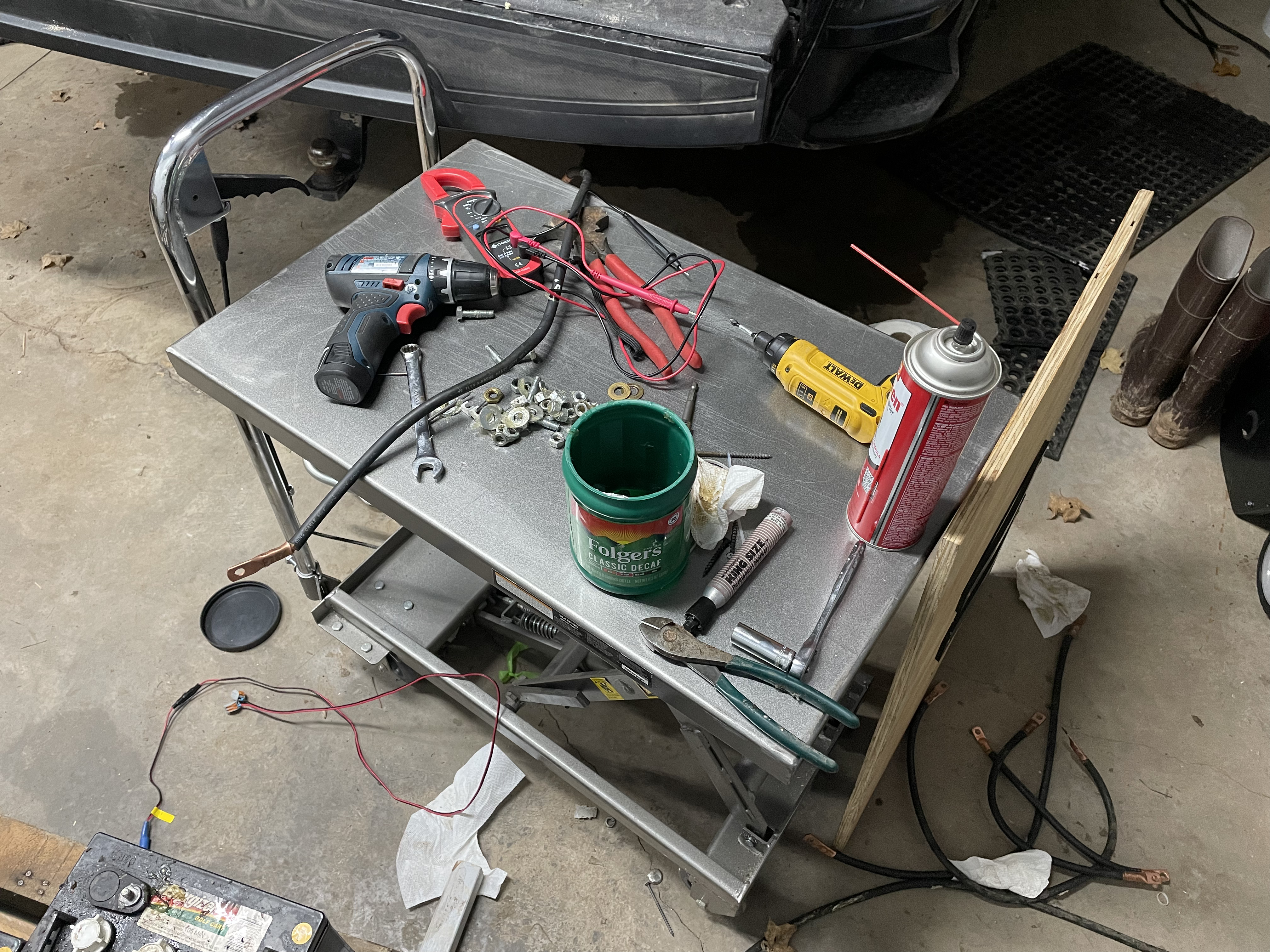
Hardware time. After some back and forth the Ol’man and I arrived at a plan for battery bank 2.0. Here is the complete parts list for the project.
Once I built out the order list I took a moment to look up some alternatives to confirm that building the battery from the cell up was the best choice. SOK was the prime alternative for the stationary battery bank I had in mind. I also included two other batteries that have competitive technology. The SOK has prismatic cells like the battery bank I built, Renogy uses pouch cells like in cell phones and the new generation of power tool battery packs, and Battle Born uses cylindrical cells like electric cars and has a built in battery warmer for low temperature operation.
I assembled one more chart before purchasing the components. The main objective of this chart was to see just what $4300 could get from each of the four options above.
Confident with the decision to build, orders were placed. Everything arrived without issue, with the cells arriving last on November 9, 2021. The same day the cells arrived I stayed up late building the battery bank. I called it a night at 2am after powering on the BMS and verifying the cells were balanced and matched as advertised. Well done http://www.solarsupplyhouse.com – you guys delivered some top notch EVE 304Ah LiFePO4 cells with bus bars and nuts, making my life much easier. The Overkill Solar BMS were also extremely easy to connect to over bluetooth on my iPhone and very well built.
Building the pack to live in an insulated, but unheated garage was the first technical challenge. The cells are encased in an aluminum shell and should conduct heat fairly well. Starting with a large 1/4″ thick aluminum plate I added an adhesive heater pad to the underside. The heater pad I used was the Facon CW-T1218, which is 12″ x 18″ with a 3mm foam pad that covers the heating elements and wiring. The adhesive is quite strong and I am certain it will not fail with time. When active, 4.8A at 13.5V provides 65W of heat to the aluminum base plate, which in turn transfers heat to the cells. While the heater pad is automatic, turning on at 45°F ( ± 5 degrees) and off at 68°F( ± 5 degrees) I wanted more specific control, and added a 12V thermostat. The thermostat is from Inkbird and set to turn on at 40°F and off at 43°F. Four hockey pucks (handy for so many projects) keep 200 lbs of battery from crushing the heater pad and are attached with permanent mounting tape.
The next major component to unbox and prep was the Overkill Solar BMS. This battery management system for 12V batteries is an impressive unit. I selected it because the manual provided is extremely thorough and has just enough sarcastic wit throughout that I enjoyed reading it:
Whatever stupid thing you do with our products after you buy them is 100% on you. There is no way to make them completely safe. We support you learning new things through research and experimentation, but a certain baseline level of technical competence and sound judgement is absolutely required. If you are completely confident in your abilities, turn back now. Fear keeps you alive
OverKill Solar BMS Instruction Manuel
Overkill Solar also tests their product before shipping. Confident I would not amputate any fingers or otherwise harm myself I continued on…
I quickly realized that I was a bit short on bus bars. The only suitable conductor I had on hand was brass. Brass is not ideal, coming in at 28% the conductive capacity as tinned copper. Brass is, however, workable with woodworking tools. I fabricated 12 brass buss bars and doubled them up so they would be roughly 4x the cross sectional area as the tinned copper buss bars included with the batteries. The studs on the cells had just enough thread to accept my home-made bus bars double stacked. Thank goodness for a well stocked shop.
Next, I crimped and soldered ring terminals on to the balance wires of the BMS. I am fast becoming a fan of using solder in as many electrical applications as possible. Soldering is cheap, easy, and highly effective at preventing issues down the road. Soldered ring terminals will never come loose from the wire whereas a simple mechanical crimp could face issues from temperature fluctuations or vibration.
Using polyimide tape I assembled the cells into groups of 4 and then into a single pack of 16. A quick and dirty wiring test proved that everything worked. The BMS checked out and the cells were indeed matched. The official “it’s alive” screen capture from my iPhone after connecting over bluetooth to the BMS. Yeah… that’s 1:34am and 2:05am… this is the exact charge state of the batteries just hours after delivery.
Electrical tape, zip ties, double sided permanent mounting tape…
Soon the battery pack was in its finished form. Even the thermostat for the battery heater pad was wired in (it’s also fuse protected).
I then got some sleep. More would have been better… but some was enough.
11.11.2021 – Thursday
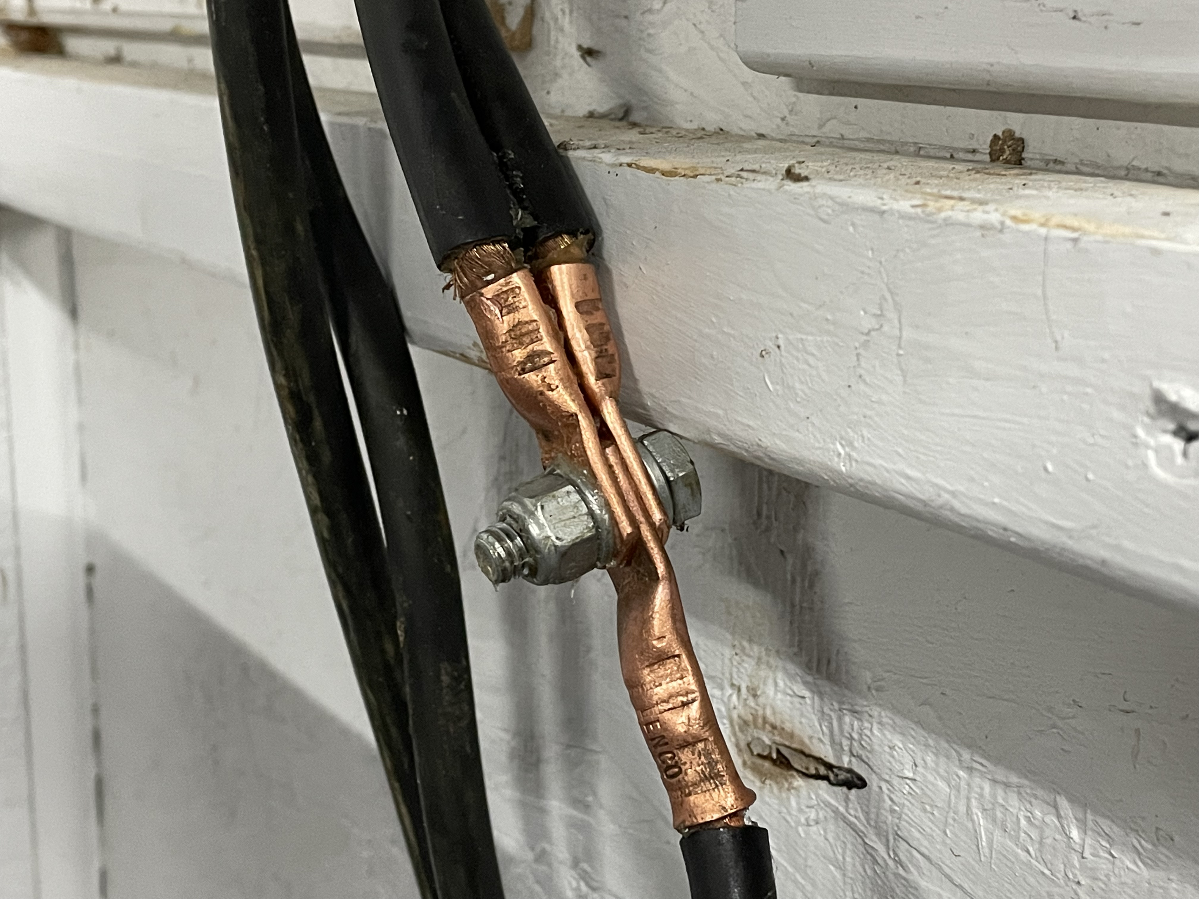
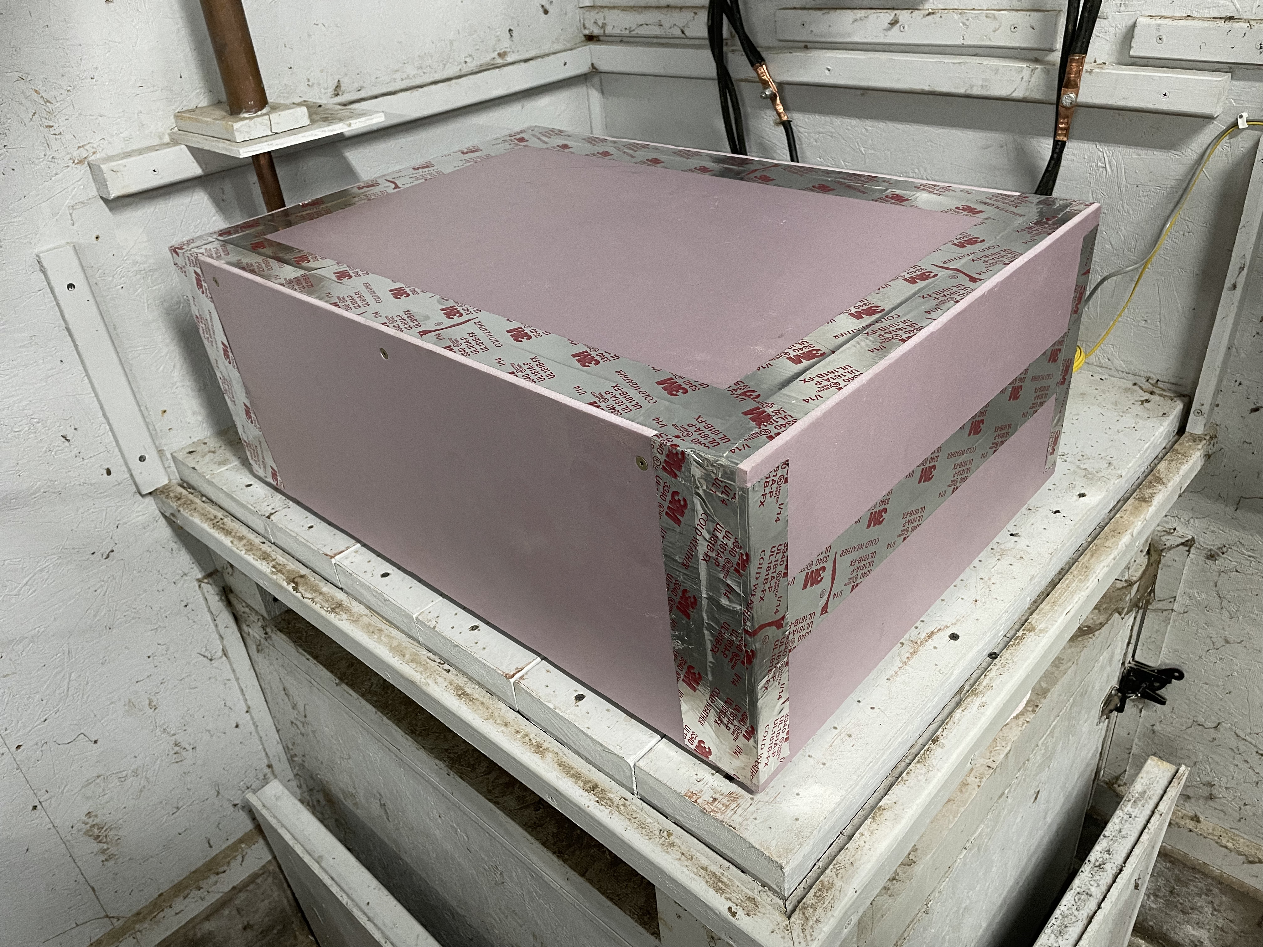
Figuring out how to transport the finished pack was a bit of a mind-bender; the aluminum base plate is not very tractive against the mating surface of the aluminum LiFePO4 cells. Let’s simply say that the solution was provided through the creative use of plywood, a rubber mat, and two ratchet straps. At camp I was able to slide the pack off the truck tailgate onto a lift table and slide it over to the battery platform in the garage. I cleaned and then reused the battery cables from the old battery bank and after two hours got things connected and properly torqued. A few cable were short of the required length to reach the buss bars on the wall. I doubled up and did my best to match the length of the four battery cables that connected the pack to the buss bars. A final touch was the addition of a styrofoam box with a 1.5″ wall thickness. It was assembled with construction adhesive, a few long wood screws, and metal HVAC tape and will be a winter-only accessory.
11.12.2021 – Friday
Is that smoke?
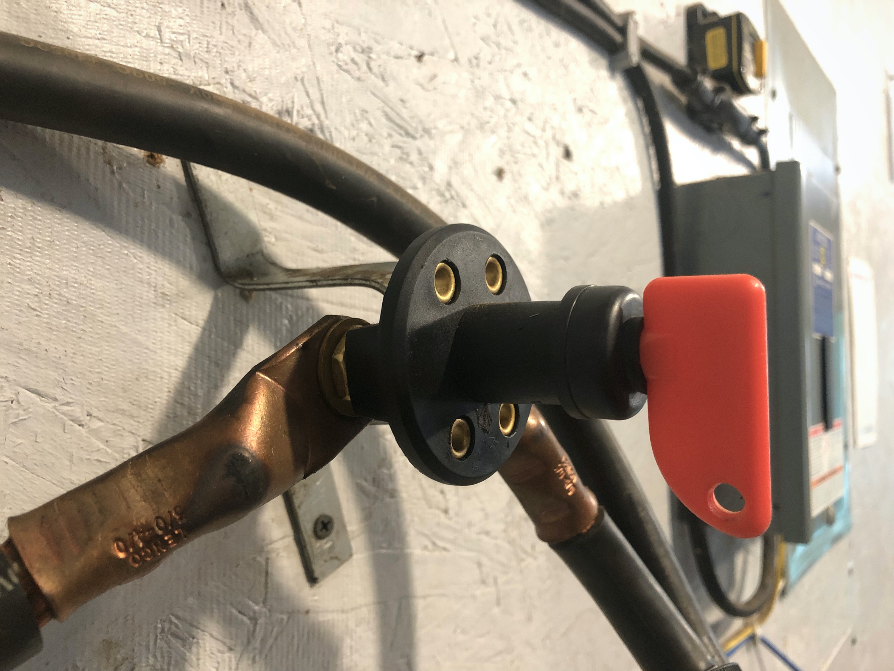
I learned something valuable today. Don’t buy electrical parts that are not UL listed (except for the Overkill BMS) because they will try to burn your off-grid garage down. A properly constructed off-grid system will defend against a failed component and should not burn down. That was the case this evening when I entered the garage and questioned why there was an odd smokey plastic smell. Not one to turn away from anything out of the ordinary, I investigated and discovered the issue. This (claimed) 500amp battery disconnect switch is complete garbage. It was purchased from amazon.com and was a ticking time bomb. Under a two hour sustained 130 A load (charging the batteries) it self-destructed. The undersized conductor burned right through and melted the plastic shielding.
After this surprise, the switch was deleted and progress continued adapting the off-grid system to the new battery bank. After reviewing some reference material and discharging and then charging the battery bank I was able to establish some settings that will work with this specific battery bank and our Xantrex SW3000 12V Inverter/Charger. The Inverter will cut out at a low voltage that leaves about 15-20% SOC in the batteries and high voltage cut out under charge will stop around 90% SOC. Operating in this sweet spot provides about 10KWh of power and allows for an estimated 5000 charge cycles and 30 year lifespan for the batteries.
Up for a three day weekend before the gun deer season began November 15, I began programming the new Off-grid cabin system settings into the BMS, inverter, and solar charge controller. After doing some research online I consulted some excellent charge/discharge charts from Youtube channel Off-Grid Garage and programmed the protection and capacity settings for the BMS. After that I began to discharge the batteries, stepping down the low-voltage cut off for the inverter until I was fairly confident I was sitting around 17.5% SOC and settled on 12.7V as the low battery cut off set point for the Inverter. Since batteries will experience a voltage drop under heavy discharge, I set a 6 minute delay so the system must read 12.7V without interruption for 6 minutes before cutting off. This makes sure that the inverter doesn’t cut out if the well pump or microwave is used when the battery bank is close to requiring a recharge.
After reaching the low SOC point, the generator was run until 80-90% SOC was reached. The same technique was used. The charge current was set to 14.4V and the charger bulk terminate voltage was stepped up until the charger cut out around the desired 90% SOC. This setting is specific to charging at 130 A for 1216 Ah of EVE 304Ah prismatic cells because the charge current and battery internal resistance will primarily determine what the stop voltage is for 90% SOC. The inverter stopped charging at a reported 14.2V current – however, the battery BMS recorded a battery voltage of 13.70V at this same point in time. Once the battery came to rest it settled around 13.30V under a load less than 150W.
Watching voltages, consulting charts, and changing settings for three days left me with an interesting observation. Battery monitor, Inverter, and BMS all report fairly similar V under discharge. Things get more interesting under a large discharge, and are wildly different under a charge current. This is why it is important to discharge/charge, let the battery rest, test the voltage and repeat until the Inverter/Charger settings correlate to the desired operating SOC range. In this case it is 17.5-92% SOC.
I still need to set the solar charge controller to play nice and not attempt to overcharge the batteries, but for now it is set at what I think will work best. Because it charges at a much lower current (0-40A normally) I have it set to a slightly lower 14.1V bulk but kept the 13.6V float. If it’s not set just right the BMS will step in to protect the batteries against overcharging.
And now for some reference charts. These are widely regarded reference numbers for LiFePO4 batteries. Unfortunately I cannot find manufacturer charge/discharge data that is more specific than a simple pixelated graph. Below is the data from the voltage table found in every off grid forum.
I can do better though. The charts and graphs that follow are specific to 16 EVE 304Ah cells wired up into a 12V battery bank. Remember, Off Grid Garage did a capacity test and shared his data – and I love data! Using his test results I have reference numbers. I’m charging the battery bank at 130A under generator power and his test is 160A (reported as 40A per cell… 130A divided into 2 batteries with 8 cells is 32.5A per cell). Pretty dang close!
I also ran a discharge of the battery bank and set the Inverter cut-out voltage at 12.7V before running a charge cycle. Once fully charged from 17.5% to 92% SOC I recorded 925Ah, which is remarkably close to the 912Ah estimated. Error can creep in from many sources and I am trusting the BMS to count amps, but coming that close to reference is remarkable! The next step is to get the battery monitor dialed in just right. But that should be fun now that I have detailed charge/discharge profiles and data-rich BMS units collecting information and streaming it to my iPhone.
It will be interesting to see how this battery bank performs. I was 23 when the first battery bank was installed and it lasted until I was 35. Just think, I’ll likely be retired when this one is up for replacement… whoa…
At 9am we rolled out. Cabin bound. At the cabin the Ol’man had a boil going. The sun was out. The temperature was rising. Soon gloves were off, then hats, and lastly jackets. The temperature rose to the mid 50’s °F. I checked out the upgrades for this year.
First up is the adjustable draft unit. The set-up is simple and wicked effective at creating a rolling boil. The blower is mounted on an adjustable stand with a steel control box. Inside the box is a 110V AC to 12V DC transformer, a motor speed control dial, and an on/off switch. All these components are connected with simple spade connectors that allow for easy replacement of any component. The 3” fan is adapted to a 2.5” truck exhaust pipe with a 90· bend on the tip that aims the air up and directly into the wood from below.
When loading the stove, the blower is switched off, the flame settles, and the boil calms down. With a strong forced air draft from below the wood (Probably around 90 CFM after pushing air through a 5 foot 2.5” diameter pipe, which is 7.85 square inches down from the 9.42 square inches fan outlet, or 17% smaller) we had a very controlled and consistent boil. I highly recommend using some sort of controlled draft on a boiling stove. It makes all the difference and allows a much finer level of control.
With beautiful weather and nowhere to be, I got to study the boiling operation today. Here come the tips and tricks!
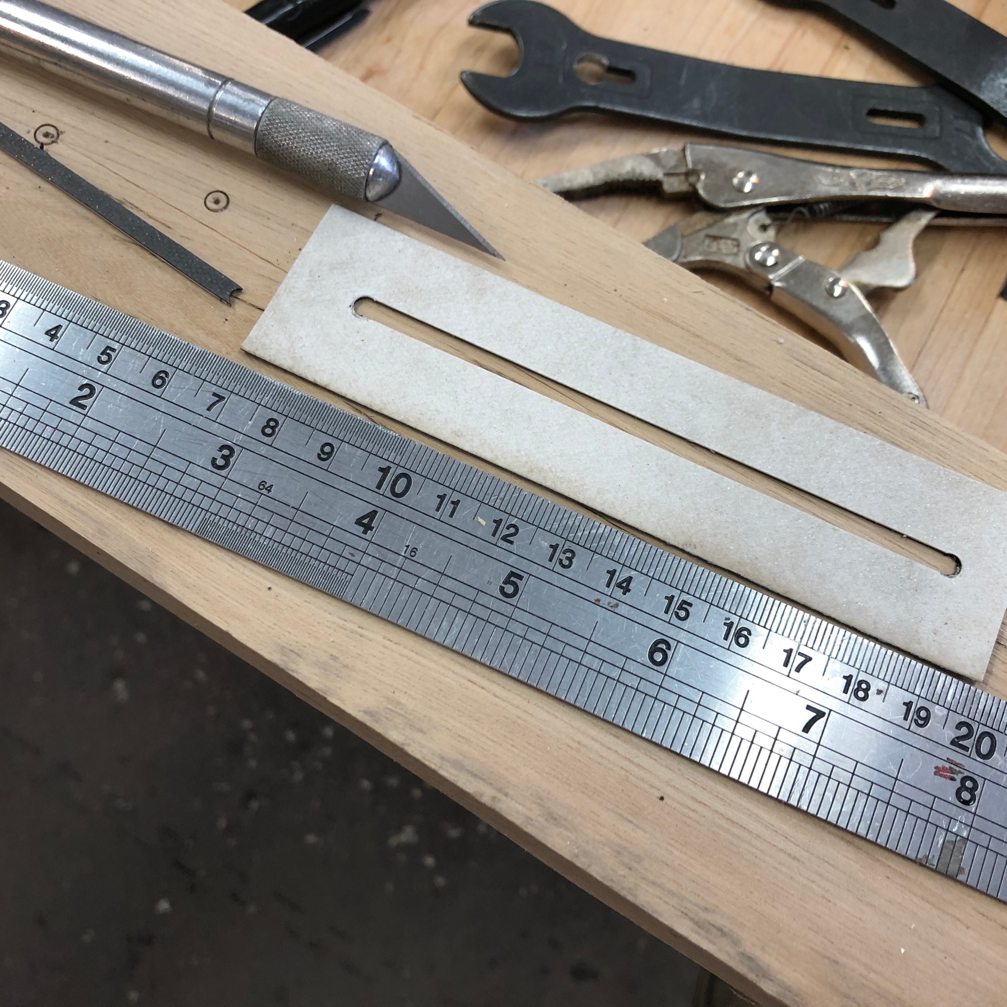
Two pieces of brass were set in the bottom of the pan. One was 2” tall and the other 3” tall. When boiling we are trying to keep the level between the two. This is a shallower boil depth that we have done in the past and the steam rolling of the pan looks very promising. Our hourly boil rate in a 24” x 48” pan was just over 7 gallons per hour.
The pre-heater pan, or dripper pan, is located over the coolest part of the large boiling pan. This location allowed for the fastest boil rate and allowed the most steam to escape. A weakness of our stove’s design is the short firebox. Because of the truncated firebox we can only achieve a strong evaporative boil over 60% of the surface of the pan.
A 4-foot carpenter level is kept nearby and occasionally the stove is adjusted. As the frost leaves the ground this time of year the stove can fall out of level. A simple bottle jack and wood wedges make for a quick and easy way to level the pan from day to day, while keeping the heaviest part of the stove over the concrete slab off the front of the garage.
Every 20 minutes the stove is tended and three things are checked:
check the boil and depth in the pan
add sap and adjust the dripper pan if needed
check the firebox and add wood if needed
Between one check the Ol’man and I made a trip down below to a corner of the property that is mostly small scrub brush. Freezing nights and receding snow cover made for the perfect time of year to survey the site. Right now the plan is to add a second pond about 50 to 60 feet in diameter in this low area. There isn’t much for deer trails or cover, and the pond would add animal habit to the property. Hopefully more on this project in the future. Prior to bringing in an excavator only light site preparation is needed. A modest trail will be cut and leveled. The excavator will be able to clean and bury the small scrub brush without first cleaning the site.
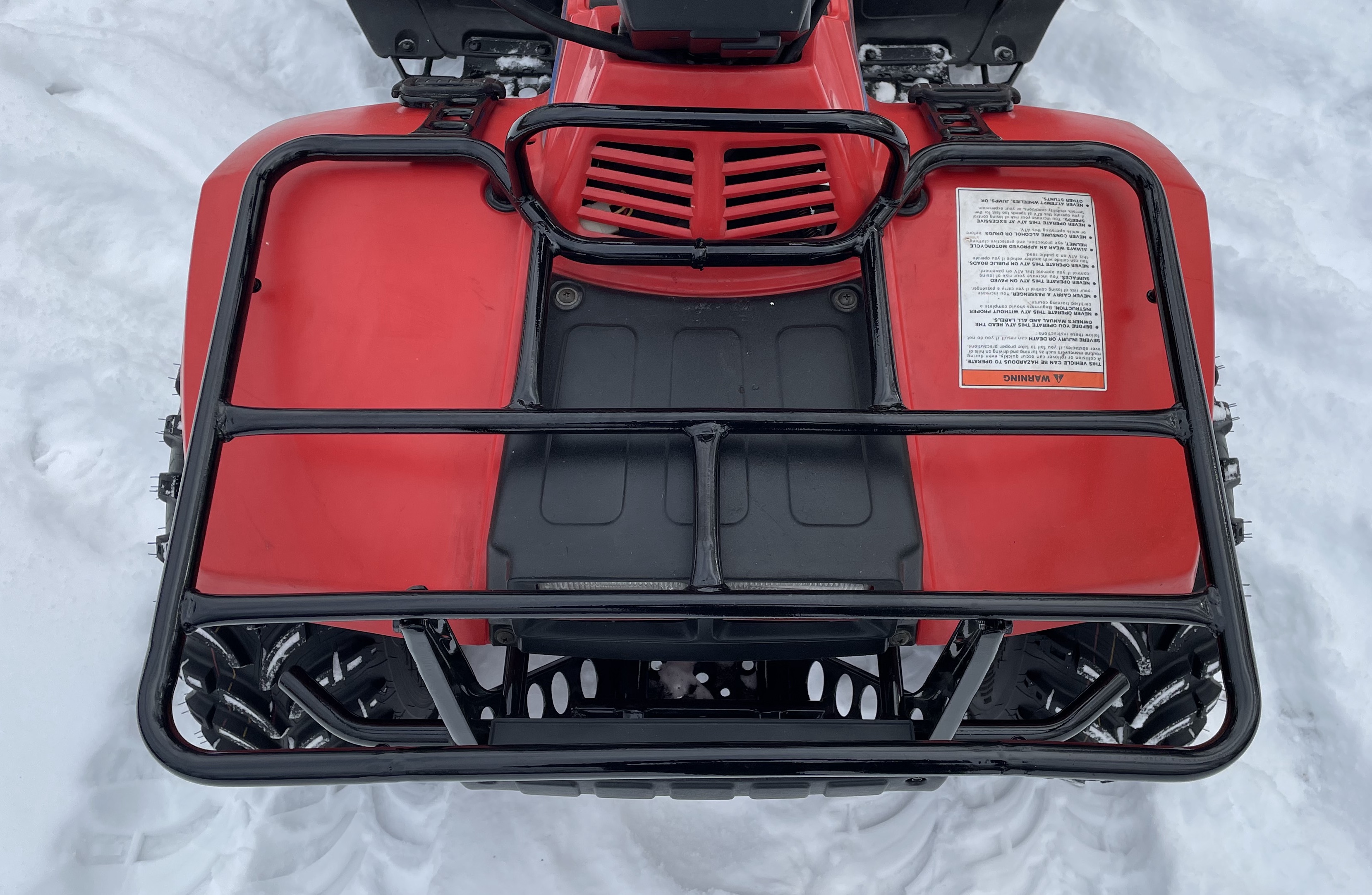
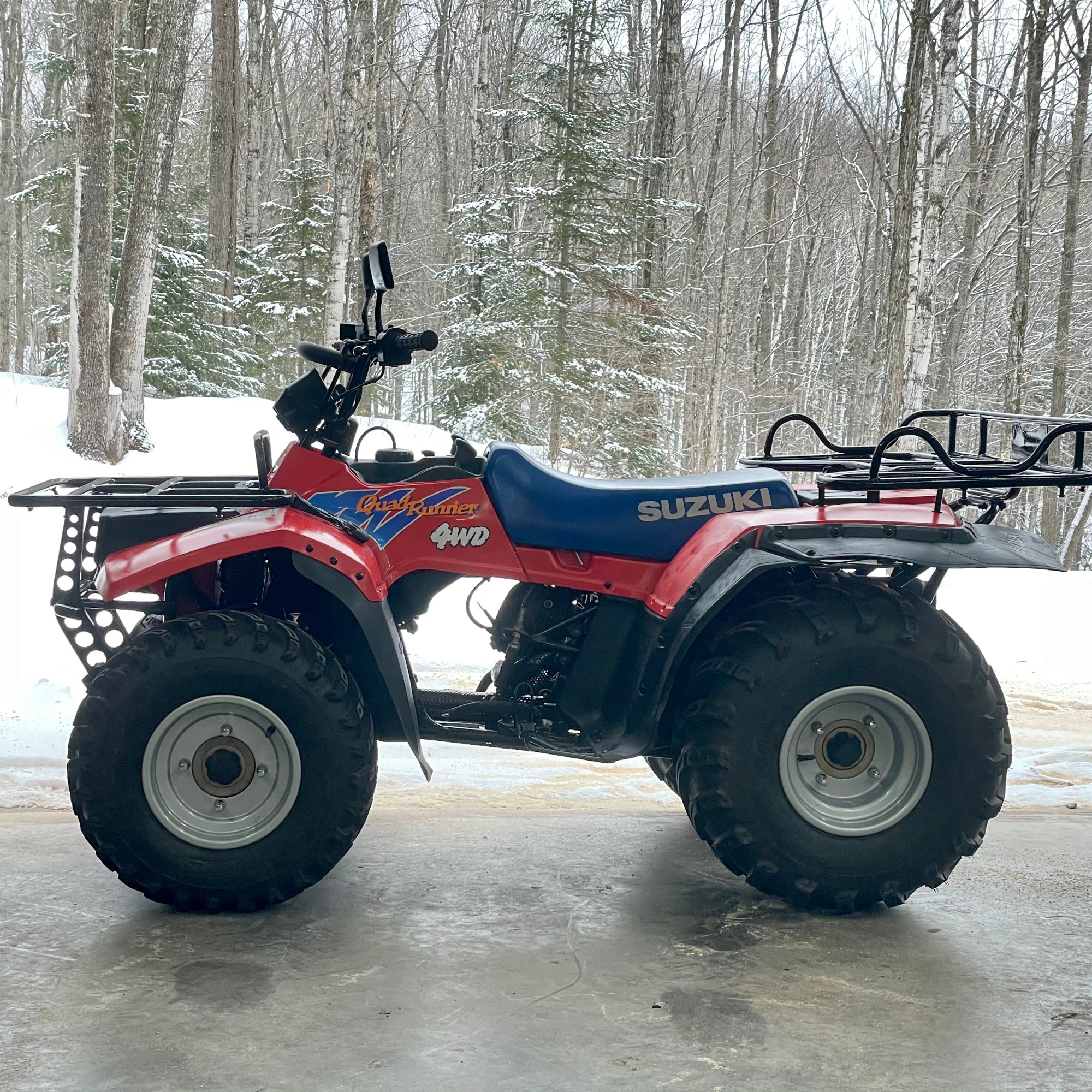
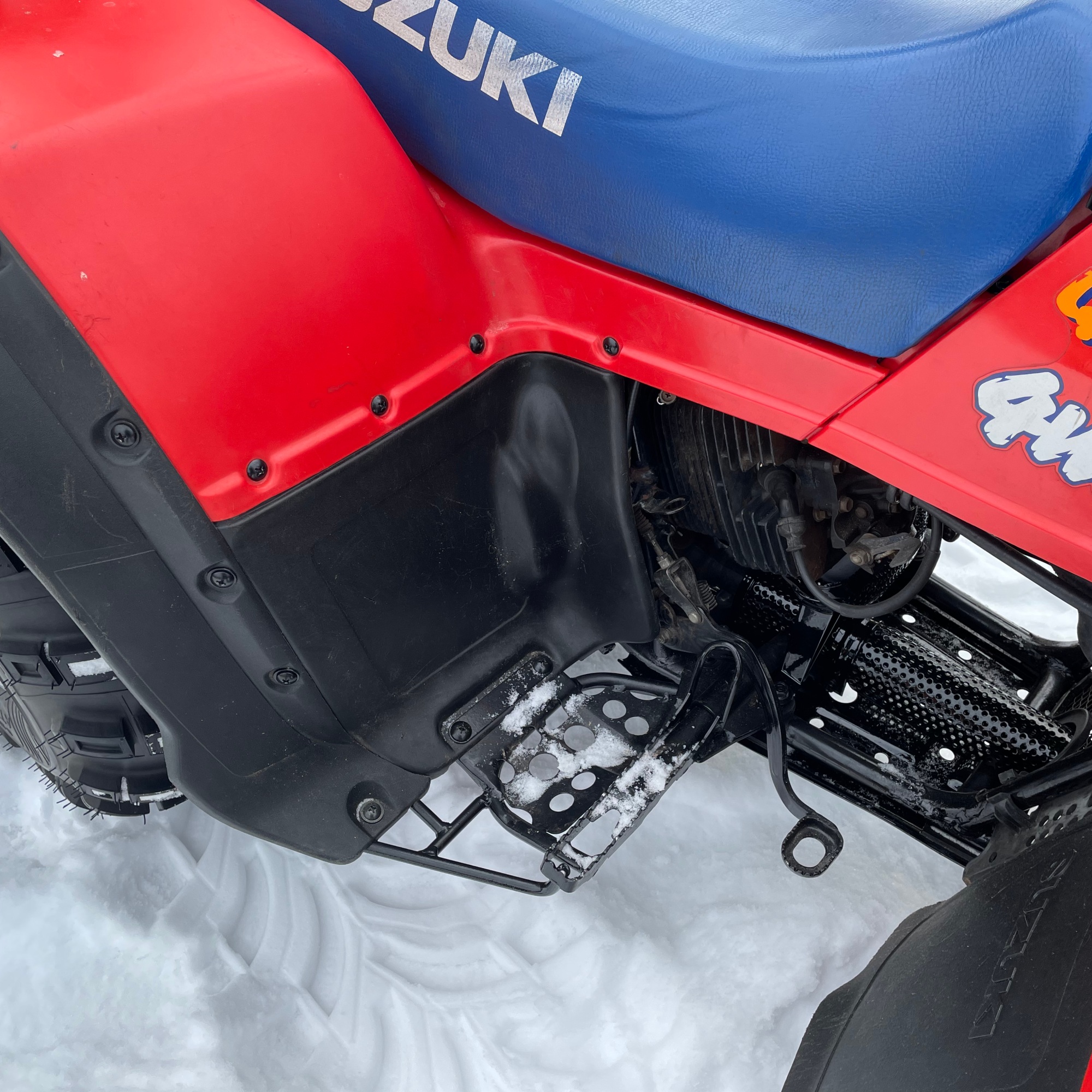
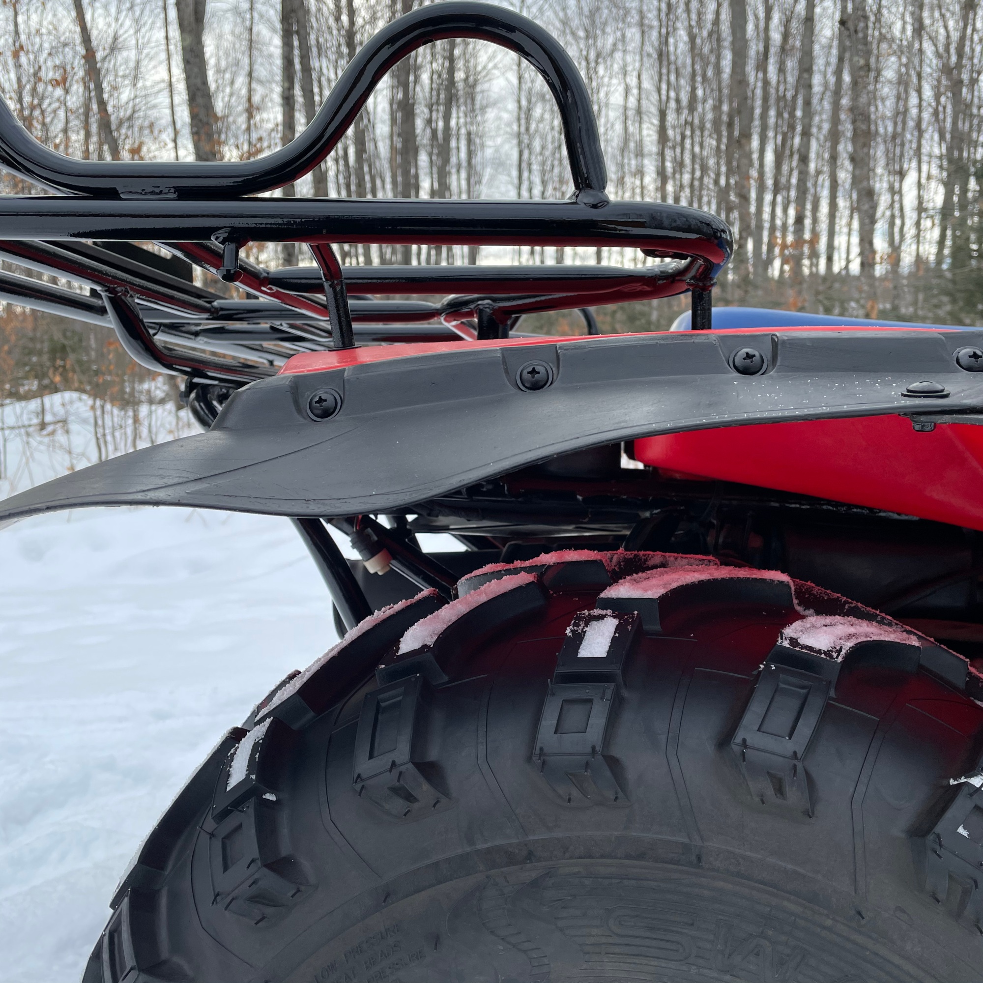
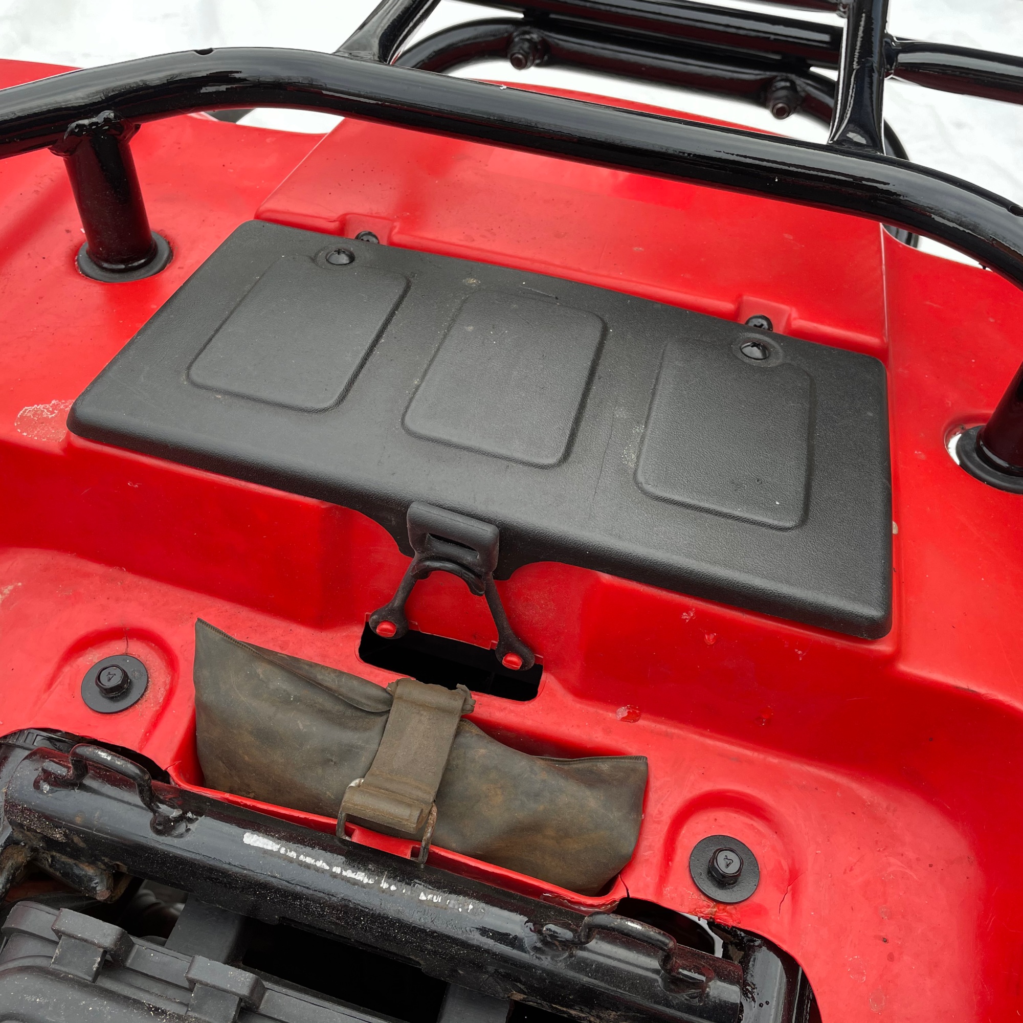
With two four wheelers at camp now, the Ol’man and I each had our own ride! The Pioneer 1000-5 side by side is set up for sap collection so having two ATV’s to run around on was a luxury. Having driven both machines back to back a lot of changes happened in the 15 years between each ATV’s development. The Honda has a fully mechanical infinitely variable transmission with hi/lo and is the smoothest transmission ever developed for an ATV. The Suzuki’s transmission is bullet proof and small with hi/lo/super low and an auto-clutch 5-speed manual. The Suzuki also lacks effective front fender coverage; so I take it slow through the mud and puddles.
One of the four cedar duck houses I built this winter with the kiddos found its way to a low spot on the property. We now have two duck houses up on the forty.
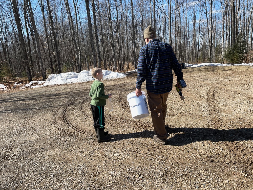
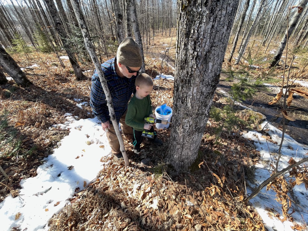
The wind settled a bit in the later afternoon and suddenly the sap let loose. The kiddos set a tap each near the garage with the help of grandpa and each of their trees ran a gallon in about 3 hours! Sugar content dropped to 40:1 from 28:1 earlier this season.
The Ol’man found an electric pump in his garage attic and put it in to use. Using a small toggle switch (left hand) the pump is turned on and off. To prevent back flow or siphoning there is an inline ball valve on the pump. Also in use are some quick-connect hose fittings. It’s a lot easier to swap hoses in the cold versus trying to twist on and off a standard connection. The gasket in this design also seals very well and increases the seal strength as pressure increases.
After the 3:30pm CST collection, three trash can were full and the overflow tank even had some. We anticipated that we had collected enough by this point to boil down for 7 to 8 gallons of syrup this year.
Meanwhile in the off-grid cabin…
Last year’s syrup was being used up. My wife calibrated her candy thermometer and then started cooking down the syrup. At 22-24°F above boiling point the syrup was removed from the stove and placed in an ice bath. Once at room temperature it was stirred and stirred and stirred.
It began as a thick liquid that fought back against the stir with great tenacity. Then it got slightly easier before suddenly locking up. After 15 minutes more of stirring a sudden transformation occurred and in less than one minute it went from thick liquid to cream with the consistency of fudge.
Think maple flavored fudge, but in this case it’s pure maple syrup – amazing maple flavor but higher sugar than fudge.
You should now be hungry (and maybe jealous). This is homemade bread (100% from scratch, no store-bought yeast) fresh from the oven with real butter and thick maple cream.
After collection, with the shadows getting long, I took a drive around to check on the taps.
In less than an hour a pint was already in most bags.
Sap was still flowing as the sun set.
Little dude got some quality outside time today!
At 8pm the last wood was added. In the darkness we could really see just how much heat that the stove is generating. This is not an infrared photo. That is how the stove door looks with a hot fire and a 3 second camera exposure in the dark.
My folks stayed, but we headed out around 10pm EST.
Our late departure was rewarded by sleeping kiddos and a surprise light show to the North. I asked Sarah if she saw those odd light streaks in the sky? With no towns in that direction, I pulled over and set up my camera and took a long 20 second exposure. It was exciting to see that first photo!
A bit further down the road we stopped once more for a better view. Holy wah! What a way to cap off the day!
And if you made it all the way to the bottom, check out a video of our day that I put together. I’m fairly new to video, but with the incredible performance of today’s phones (iPhone 12 Pro) it’s fairly easy to take high quality video. I may need to work on audio though – it was windy and that came through on the video.
A few days later the syrup was finished. The Ol’man sent a few photos of the process and reported that this year yielded 8 gallons after some spillage.
The Ol’man and I have been philosophizing about the ideal small four wheeler for a while now (3 years maybe). Something 250 to 300cc with four wheel drive would do nicely. So we started looking around…
The closest thing we found was the Honda Recon. It’s a gorgeous machine! It is 229cc with a five speed transmission and comes in at a petite 434 pounds curb weight (with fluids). But with only 2WD it’s not ideal for our needs. It’s also $4200 at our dealer. To get to 4WD the most budget friendly Honda is the Rancher: 420cc, 580 pounds curb weight, and $5500.
In other words, what we want simply doesn’t exist new from a major manufacturer. It once did, but is now long extinct. A Honda Recon is a fine machine… and there were a few almost-purchases on some used machines. That is as close as we got to adding a small four wheeler to the stable. And then…
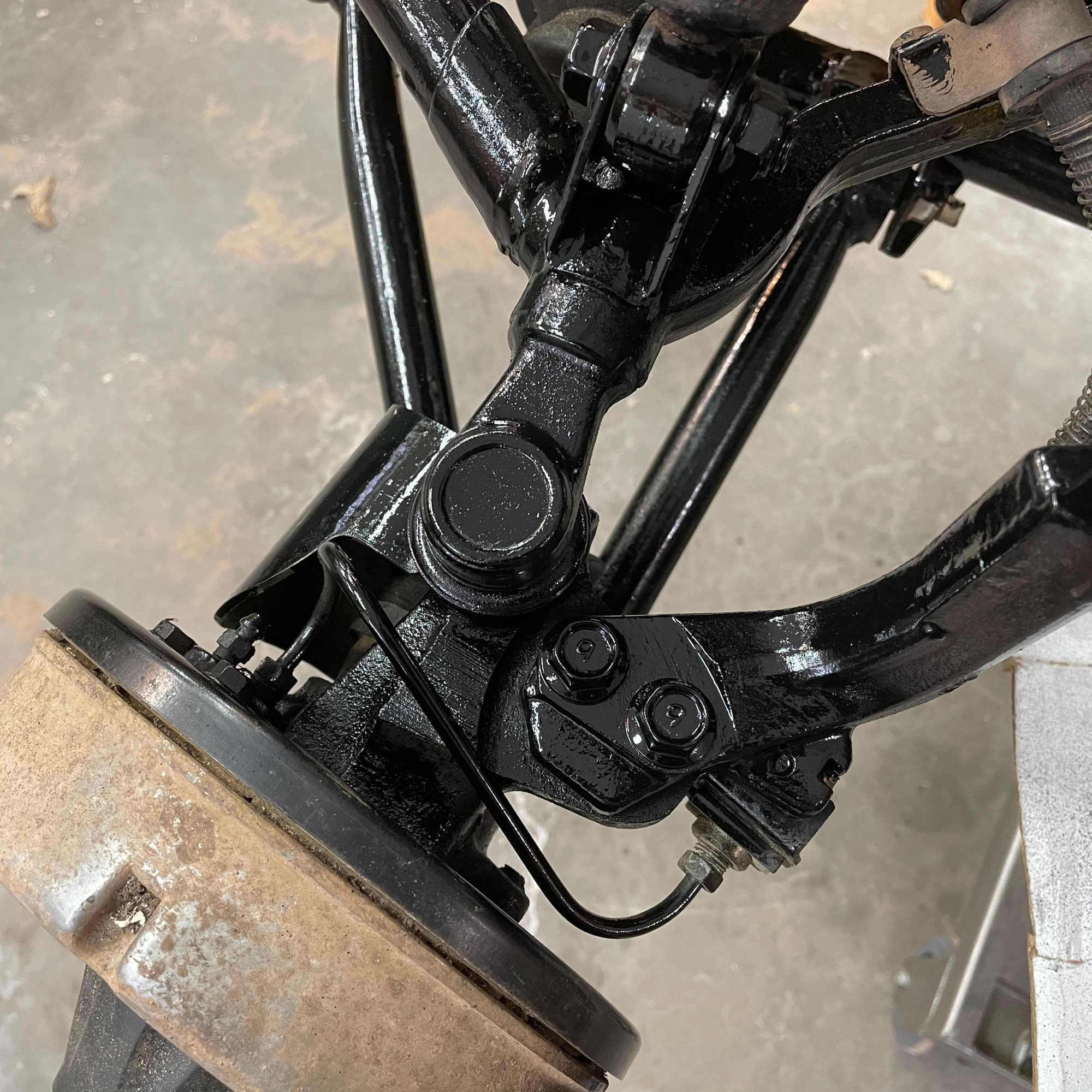
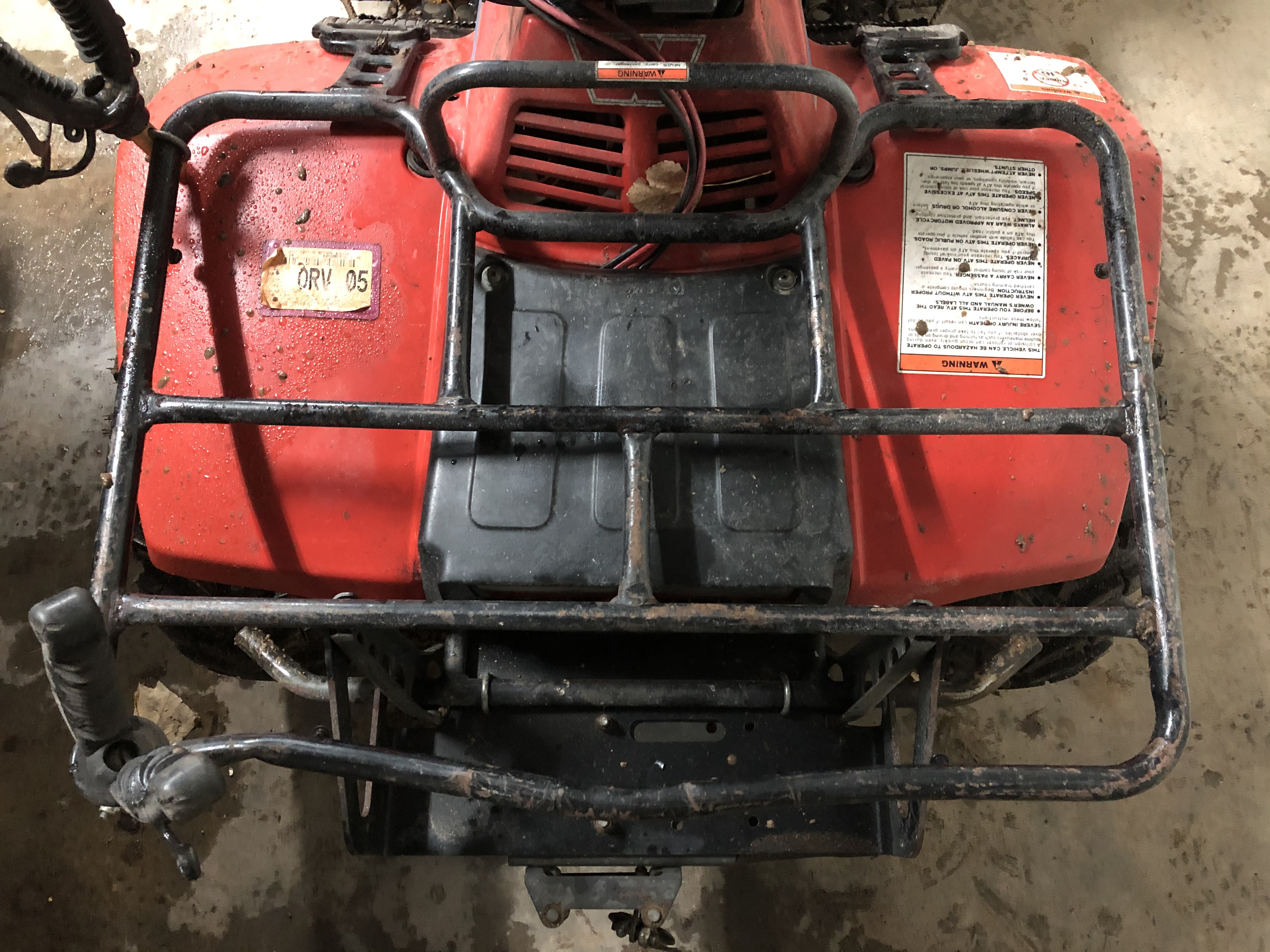
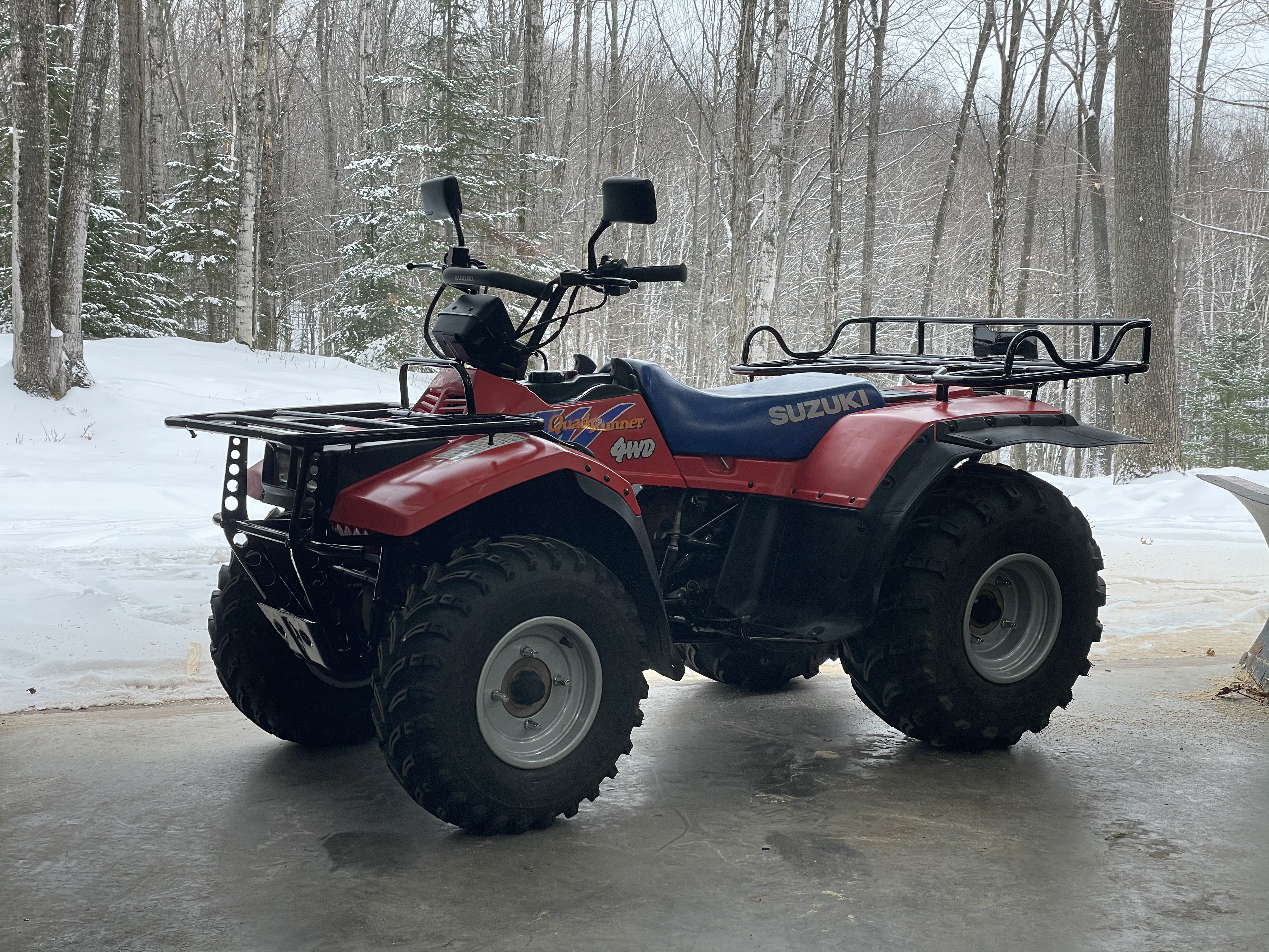
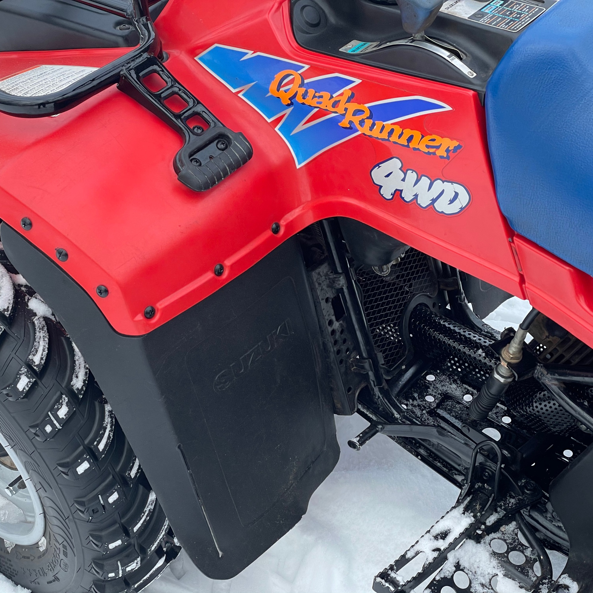
Our cabin neighbor offered up his 1992 Suzuki LT-4WD Quadrunner to my Ol’man and me. We graciously accepted and I set to work. This ATV first showed up in 2012 here. Good thing I don’t put much stock in first impressions.
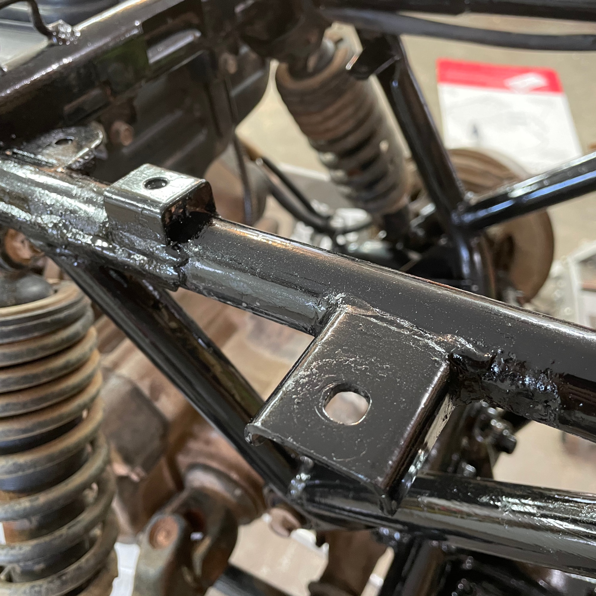
On to the restoration! I started at the very end of October, took a break in December, and then wrapped it up in January. Along the way I scanned the original Owner’s Manual and tracked my time and money meticulously. The Ol’man backed the project and I supplied the labor. After roughly $1250 in parts and services and 60 hours of work the ATV was fully restored.
10.31.2020 – Saturday
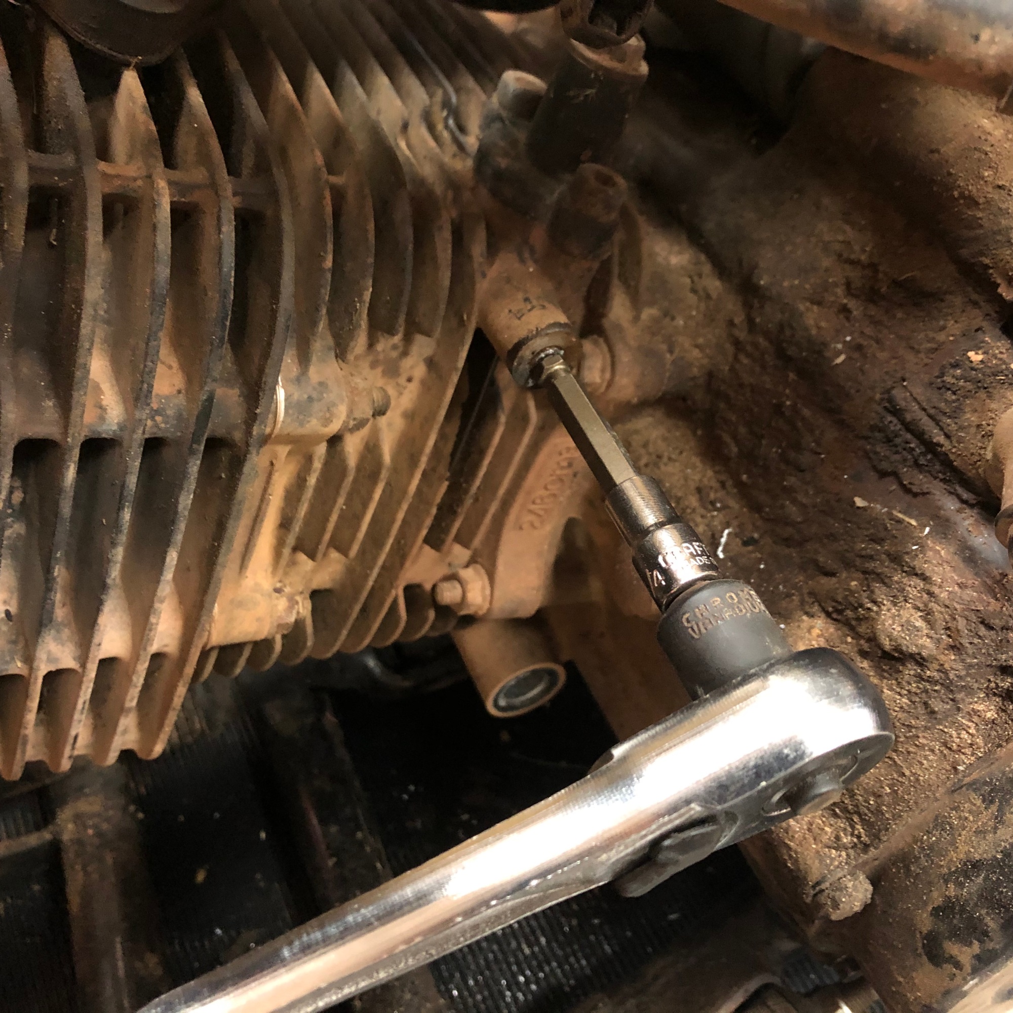
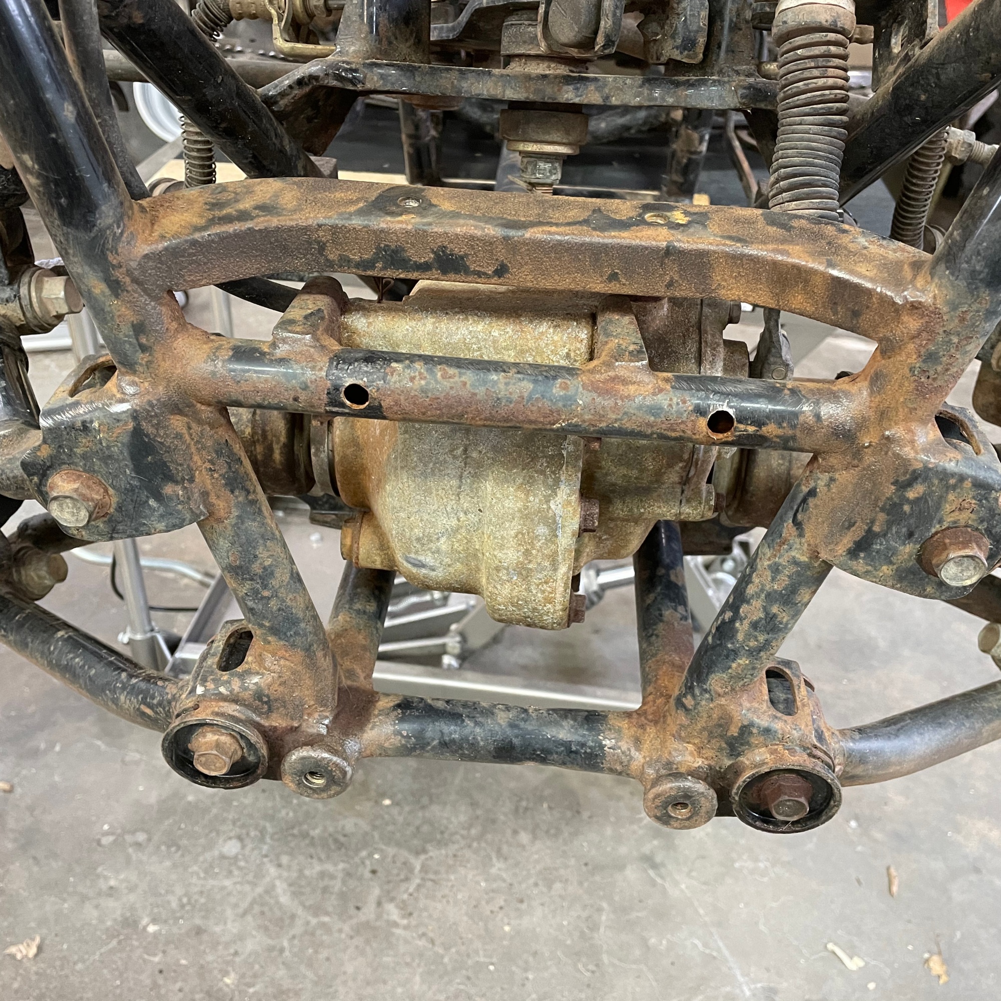
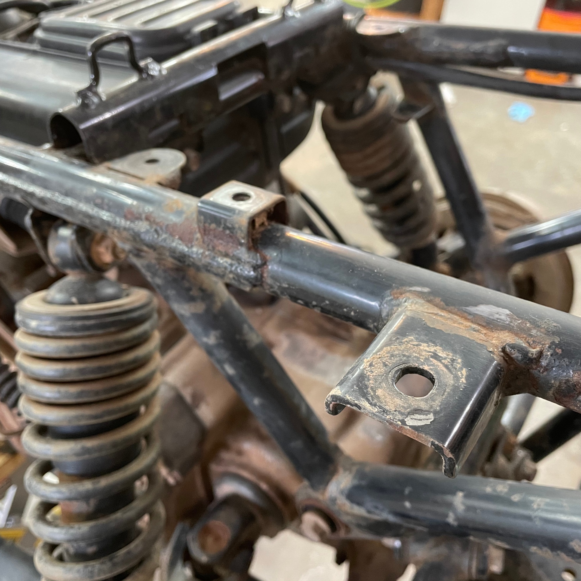
Once I got the ATV up to my shop I tore it all the way down to the frame and started making an inventory of parts to order. The hot water faucet on the outside of my garage shop was fantastic when combined with a Ryobi electric pressure washer. The ATV received several sessions of soap and power wash. After shedding several pounds of gunk the tear down went smoothly. A few bolts were snapped in the process but all were able to be removed with an extraction socket set from Rocket Socket – this set (made in USA) was a pretty great new tool purchased just for this project. A few bolts could not be extracted however, but they were drilled out before using a tap to clean the remaining shards from the threads.
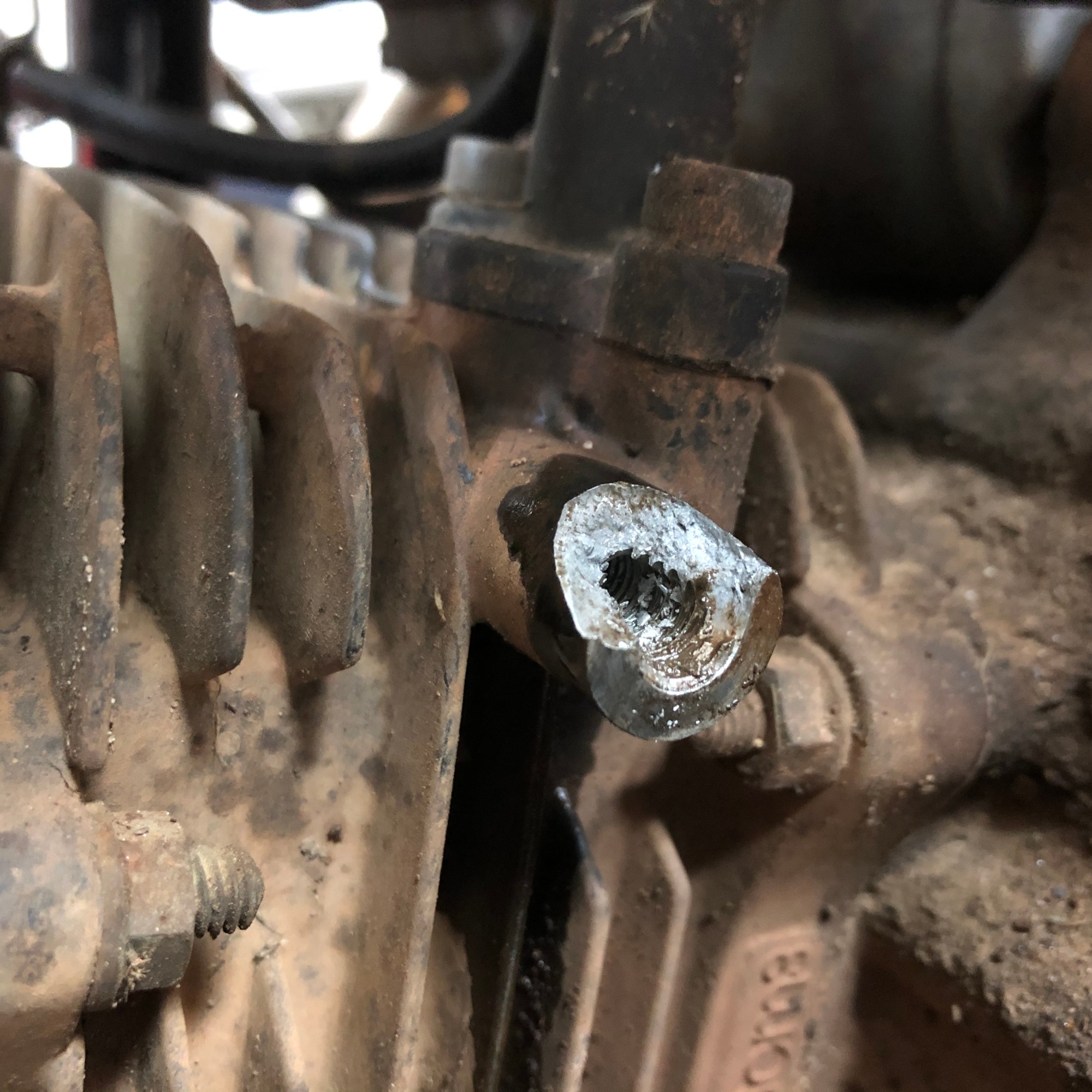
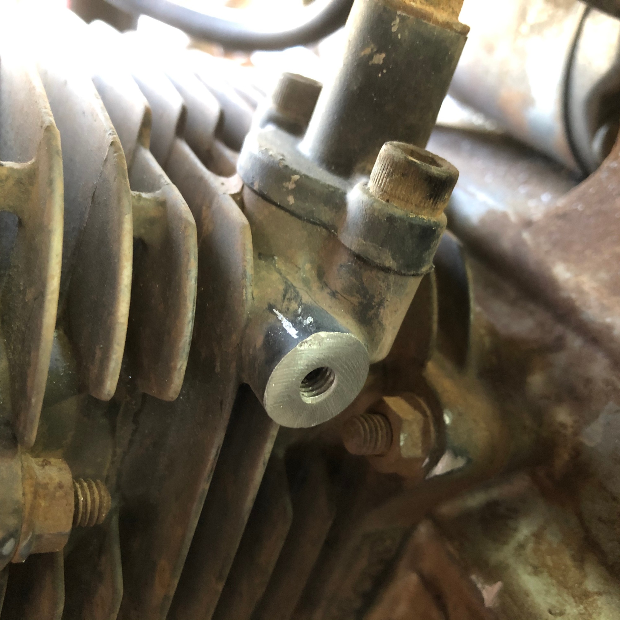
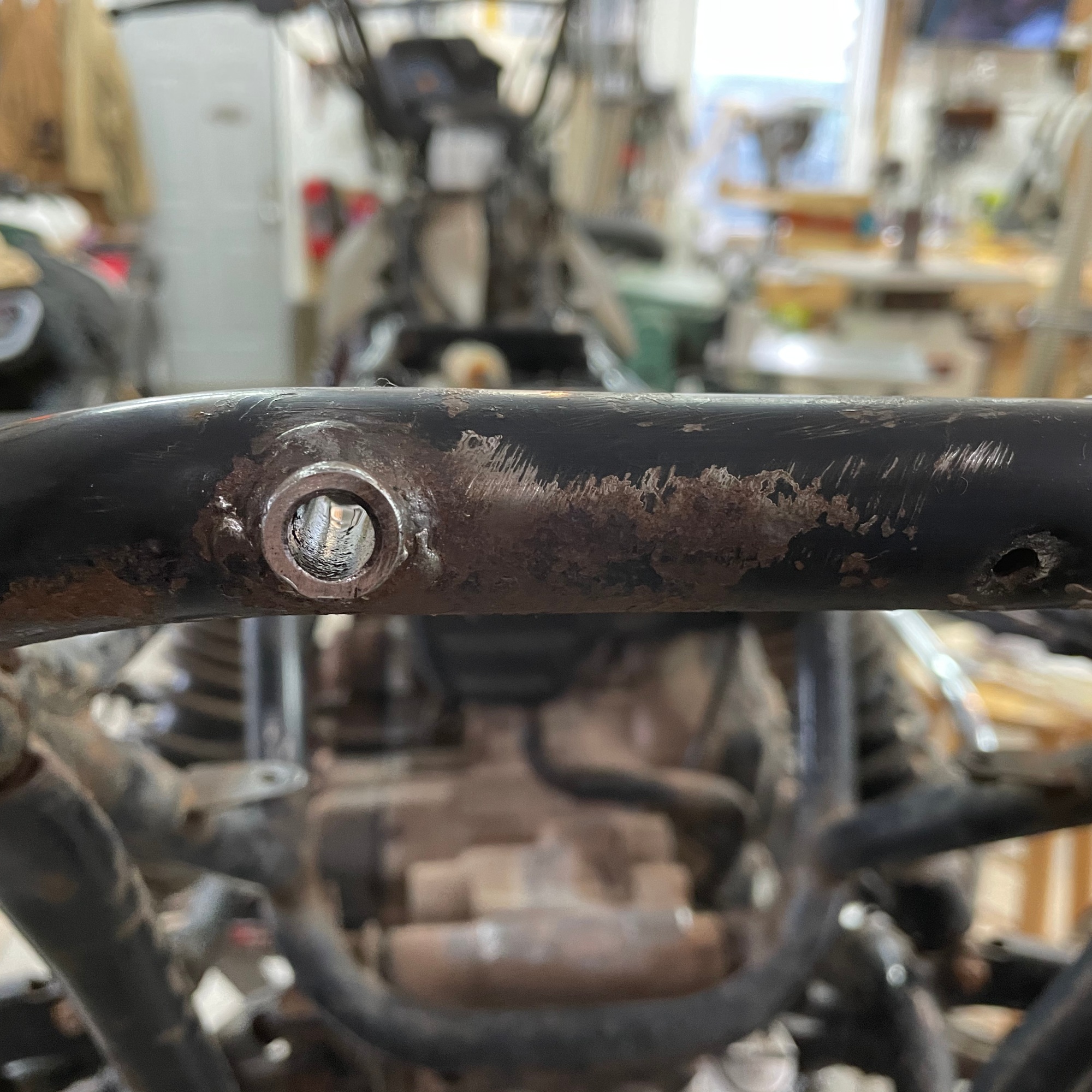
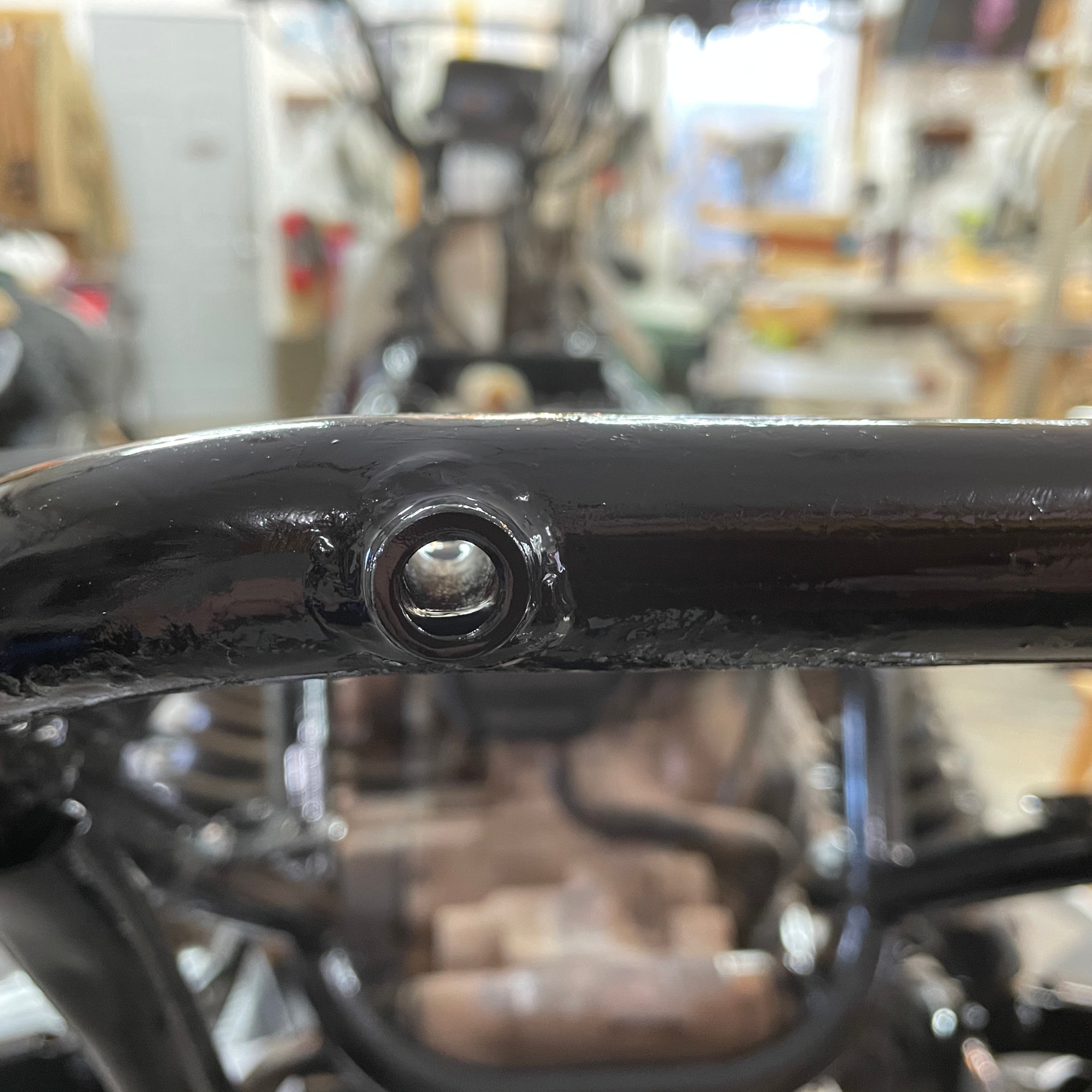
The four wheeler originally came with an unsealed lead acid battery. The two bolts securing the front plastic body to the frame were at the bottom of the battery box and were horribly rusted. The heads snapped off with little effort from the extraction socket. Conveniently, the body could be removed revealing the rusted bolt shaft. There was enough length on the bolt stud for a smaller extraction socket to gain purchase to torque it out. Only one bolt gave me a quality fight. I ended up snapping it off, leaving the stud flush with the engine casting.
Below is how to extract a snapped off bolt in an engine casting incorrectly. I drilled the center to the steel bolt stud, and then used a screw extraction bit. The bit ended up splitting the bolt and cracking the casting. Luckily, there was plenty of metal left for a longer bolt to find threads. The was field down and the resulting gap was shimmed with a few steel washers. Always drill and tap broken bolts if there is not enough of a stud for a socket extractor to grab. Also, when removing old bolts a correctly sized impact driver is far better than using a socket wrench or breaker bar – the impacts are more likely to loosen the bolt where a long gradual pull on a bar tends to snap the bolts. Lesson learned.
11.5.2020 – Thursday
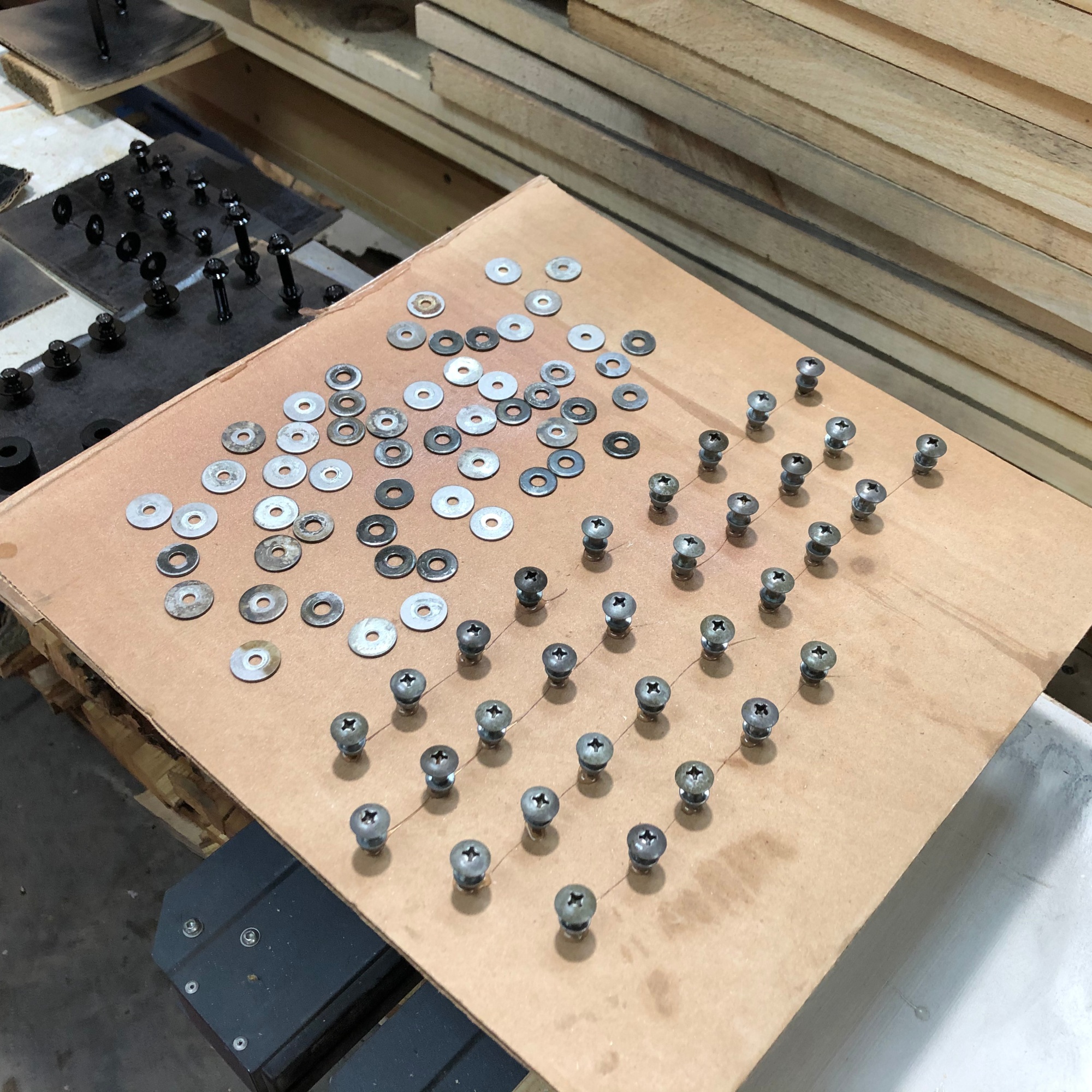
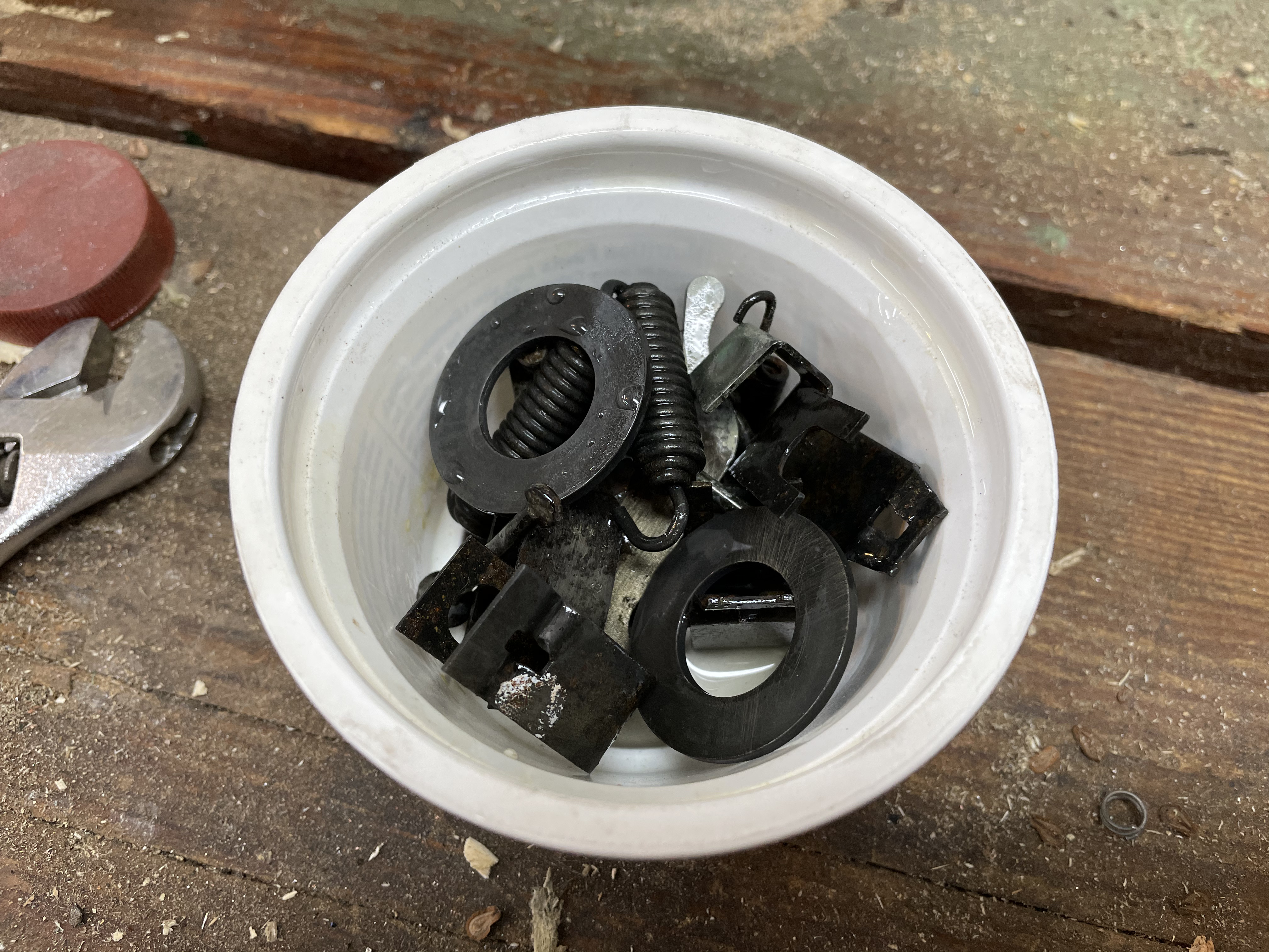
Unlike a modern ATV, there were no pop rivets anywhere. Instead there were dozens of shouldered cap screws with washers and lock nuts. Replacing these with new parts would have run somewhere around $400-500! Originally these fasteners were all black oxide coated. The coating deteriorated. Evaporust had proven useful for my previous metal restorations so I labeled a dozen plastic tubs according to the location of the ATV the fasteners came from, and then filled each with the rust removing solution. An overnight soak followed by a scrub with warm water and dish soap resulted in some paint ready parts.
11.17.2020 – Tuesday
I wasn’t interested in learning how to apply a black oxide coating so I went with black paint. A dab of hot glue on a sheet of cardboard held the machine screws upright and made the process of applying paint much easier. I applied two coats to all fasteners.
1.5.2021 – Tuesday
A lot of work has happened and now it starts to look like I’m actually doing stuff. I’ve sourced parts, sent parts to be sand blasted and painted, got it running, and tore it apart. Forty hours of work in and now begins the last 20 hours when it all comes together.
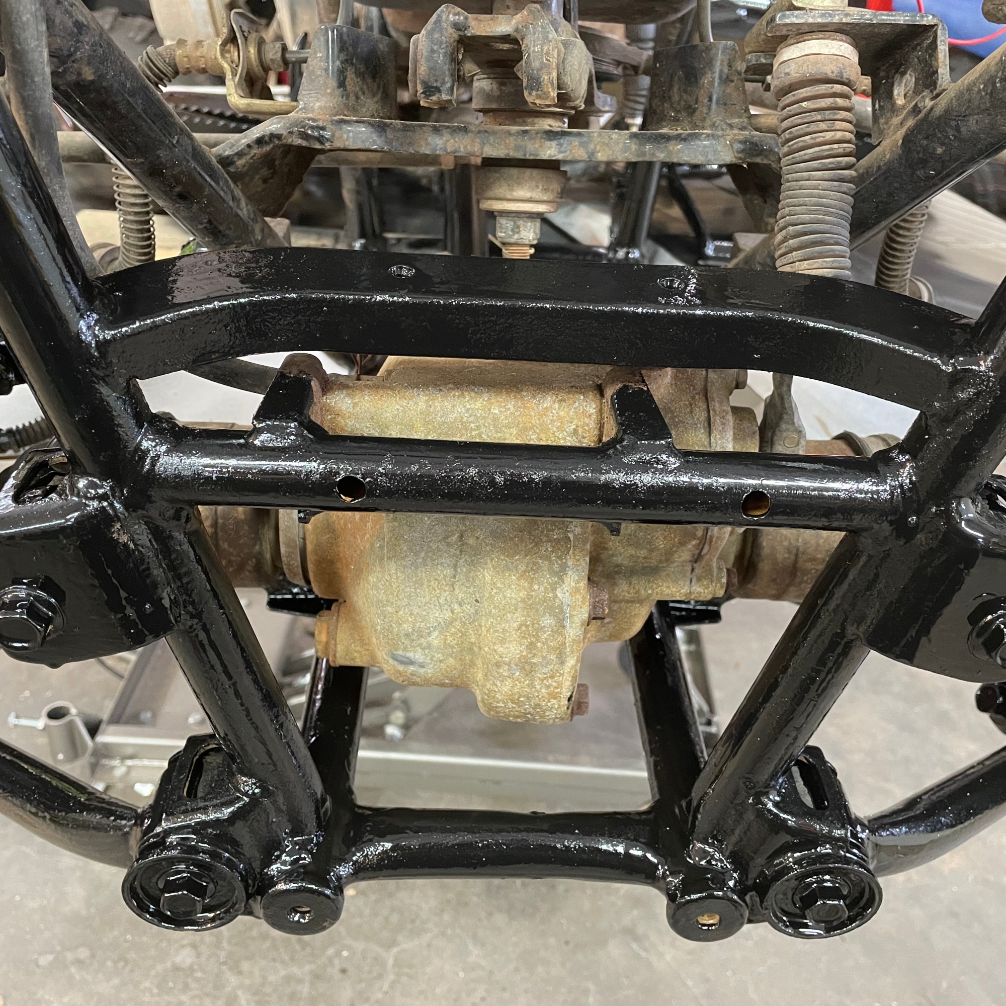
Today the frame was wire brushed, sanded, and cleaned before painstakingly brushing on a thick coat of black paint. Most of this will be hidden under plastic so it’s primarily for preservation. The pretty bits that will be bolted on later were professionally painted.
1.9.2021 – Saturday
The four wheeler came with good plastic, but parking it outdoors under a lean-to for almost 3 decades takes a toll. An inspection suggested a wandering porcupine got intimate with a few pieces and sharpened its teeth a bit. A stick also went through a mud flap. Luckily, a salvage yard supplied one part that was in pretty rough shape, but other parts were too scarce or too costly to replace and needed repairs.
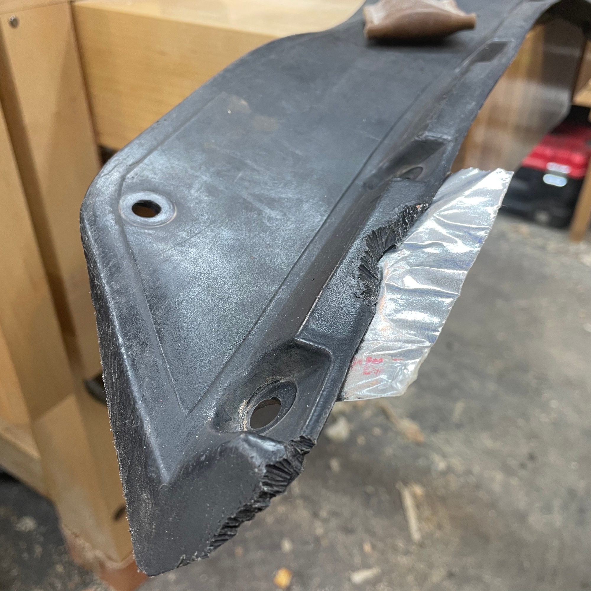
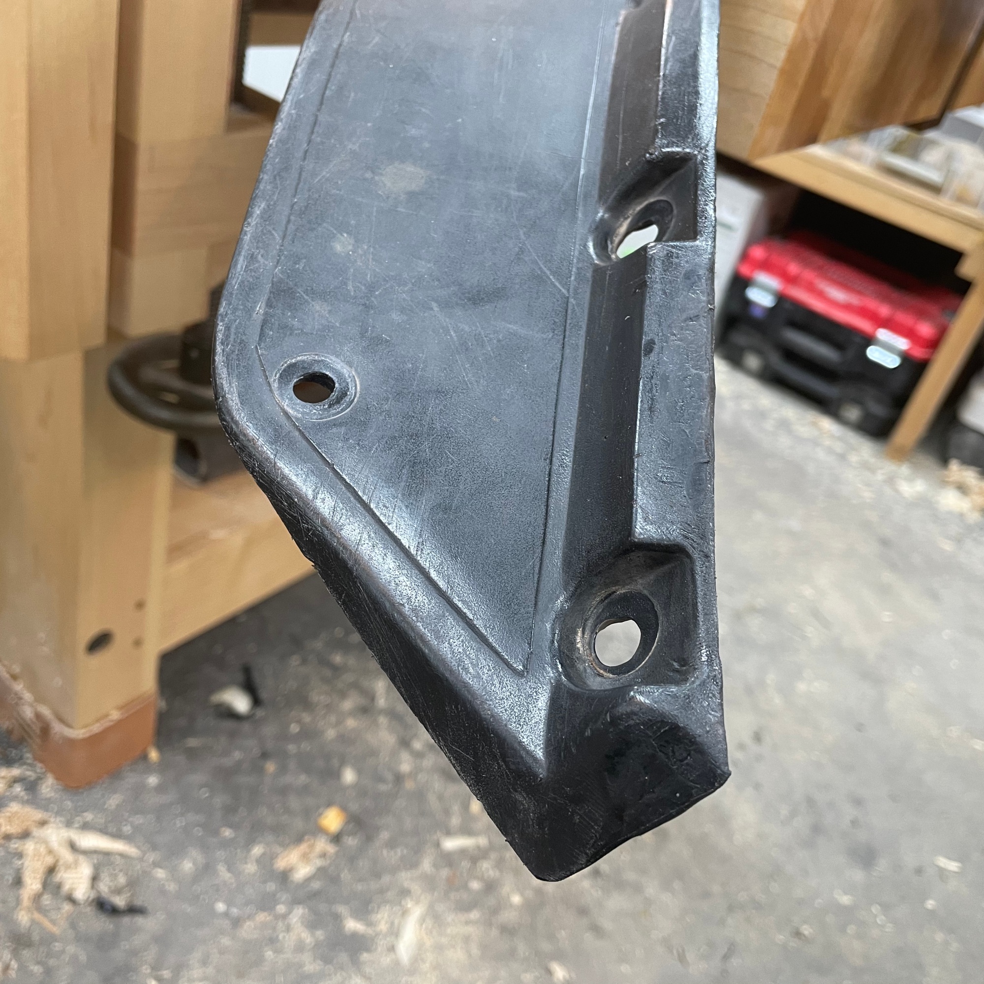
The first task for plastic restoration was to rebuild and repair. Black fender trim and mud flaps with gaps or tears were mended. I purchased the Polyvance 5700HT Mini Weld Model 7 Airless Plastic Welder for this task. The kit was well supplied and by reading through the included materials I was able to hit the ground running.
The black plastic is softer and more pliable than the colored body panels. This makes it easier to repair and easier to hide blemishes. Using metal HVAC tape as a backing, repair plastic was melted into the fender flare and then shaped with a sharp knife. Fine shaping was then accomplished with sand paper. Once the repair blended in nicely, the surface was flashed with a heat gun at 1100°F to smooth the finish and blend it nicely.
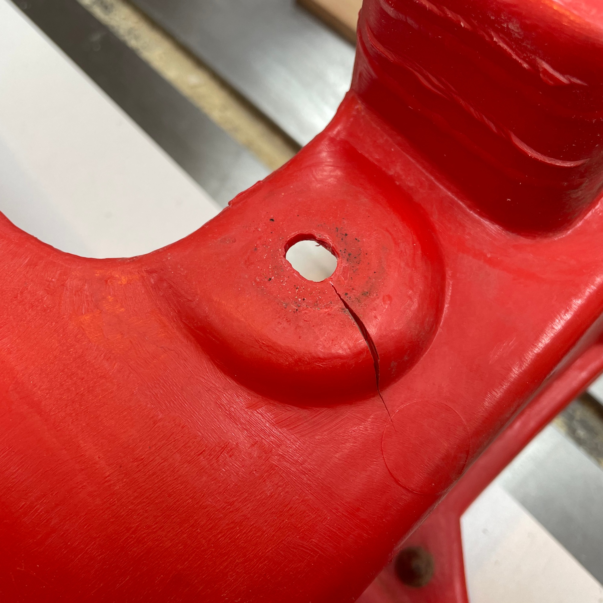
The red body panels have cracks at most of the frame attachment points. I’m not sure the cause of this. It could be a combination of temperature changes and overtightened bolts. To reinforce the cracks, a stainless steel mesh was melted into the body and then some fresh plastic was welded over the mesh for additional strength.
1.10.2021 – Sunday
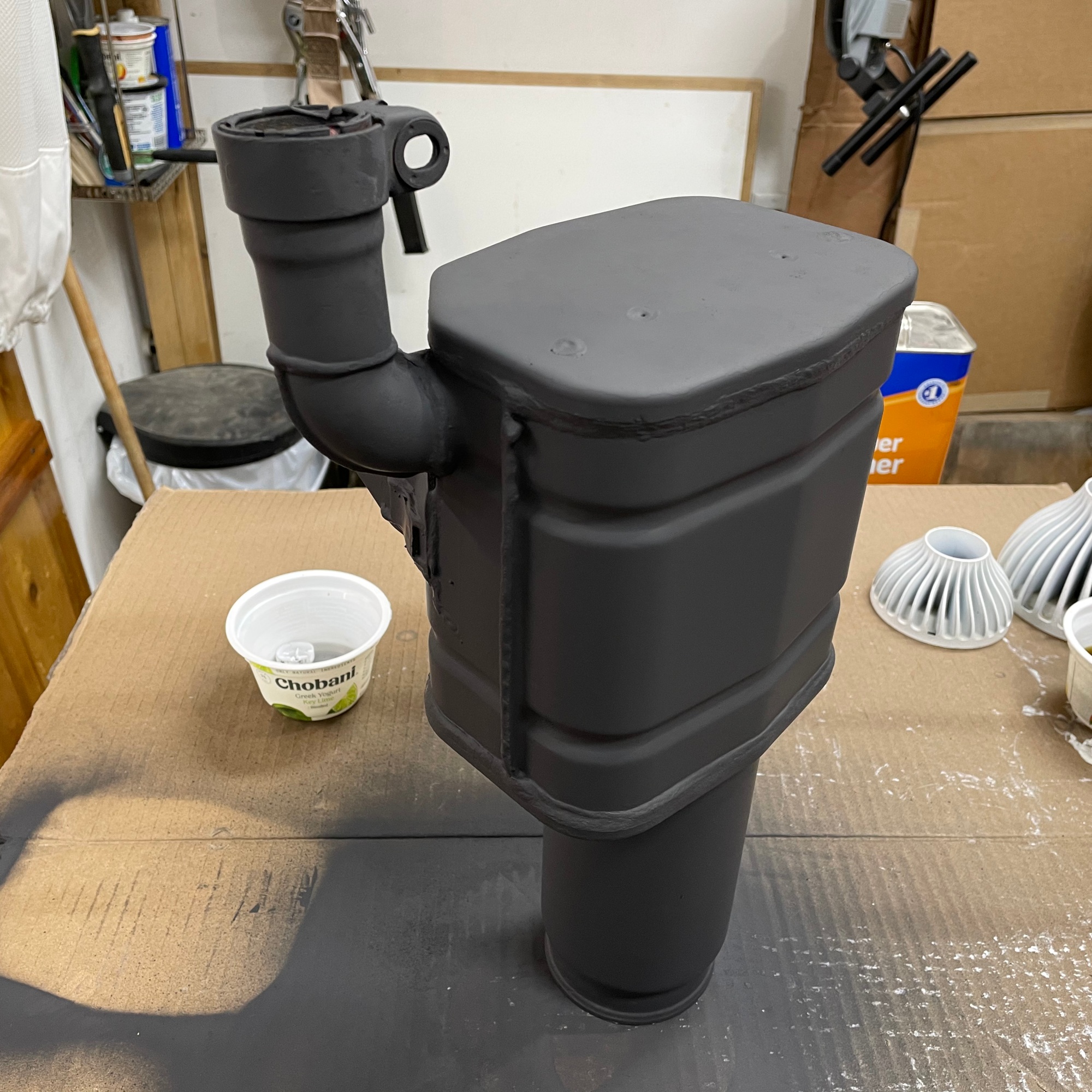
The muffler was a wreck. After sourcing a replacement from a salvage yard it was sleeved and returned to me. The sleeve weld looked… rough. I massaged it with a die grinder before stripping the paint off the muffler and prepping for paint. A matte black high temperature paint was applied prior to installation.
1.13.2021 – Saturday
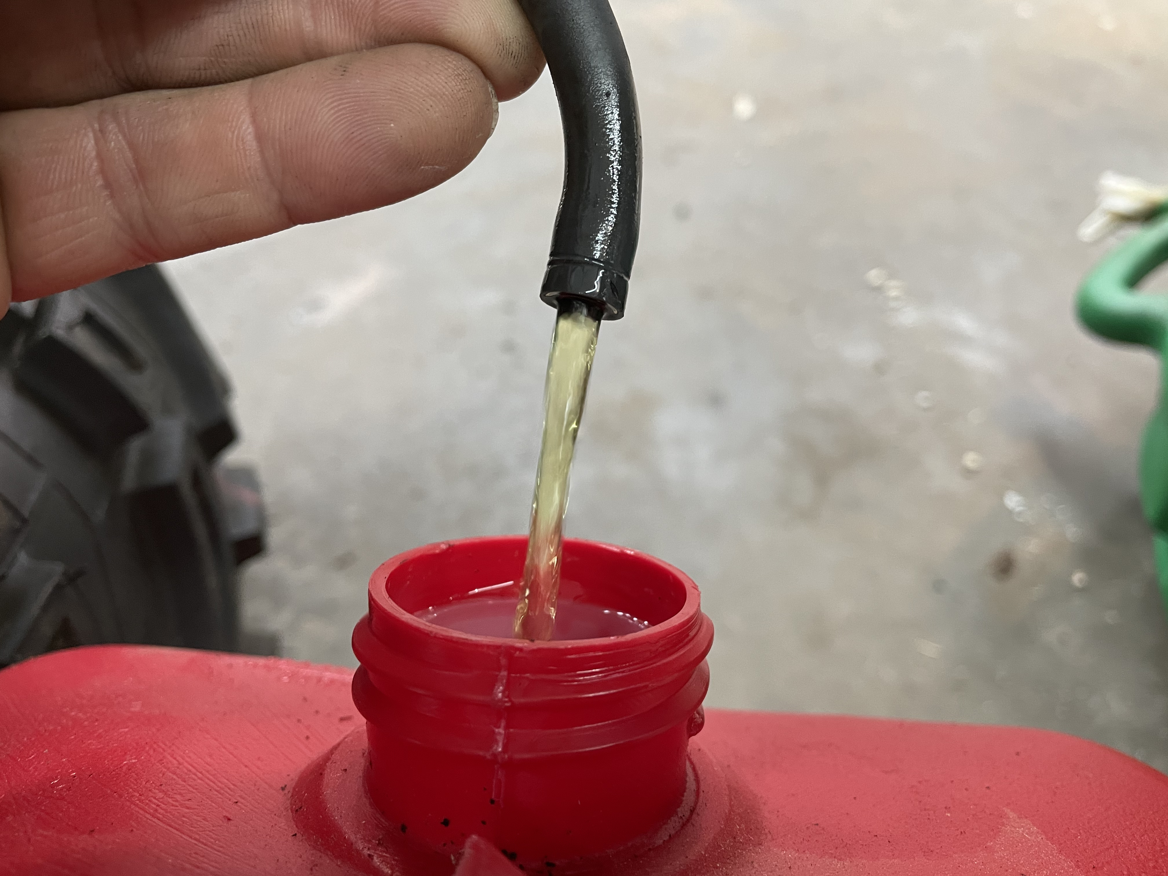
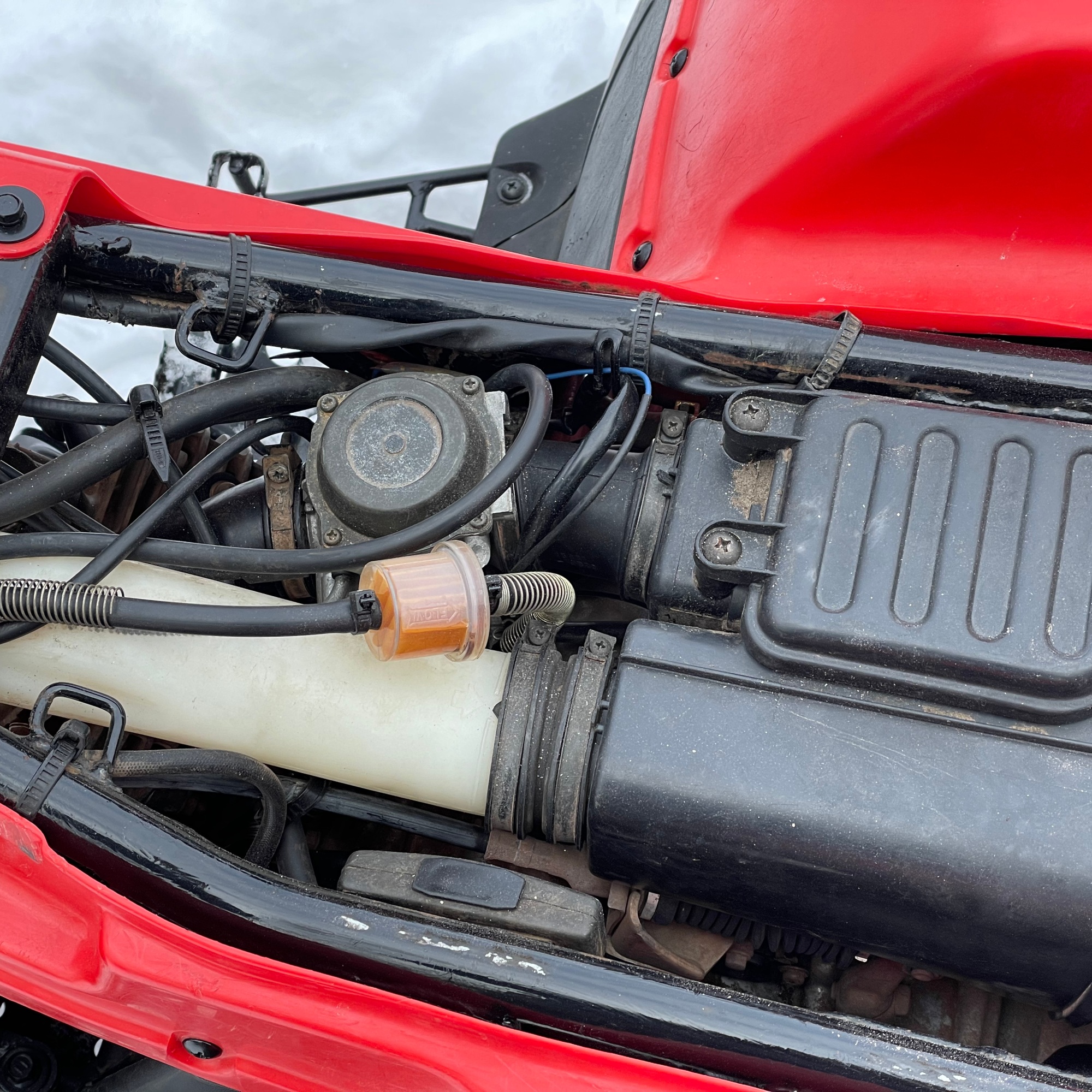
Ethanol sucks. The old Suzuki was certainly fed E15 and it suffered for it. All the fuel lines and any synthetic material the gas touched was damaged.
First up was to drain the bad fuel from the tank. After that I removed all the hardened rubber fuel lines and replaced them with soft new rubber lines. That was easy and very satisfying because it went exactly as planned.
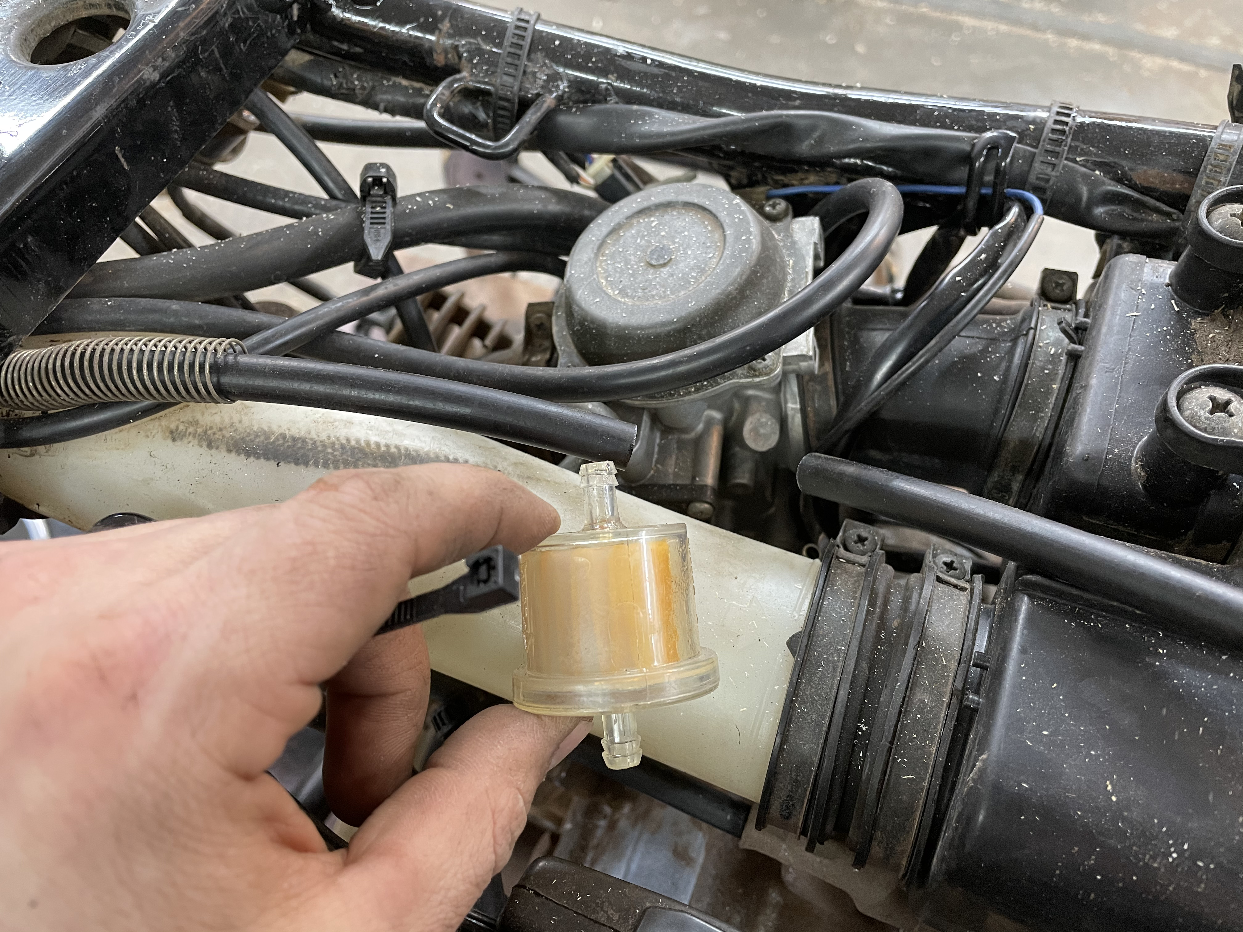
The fuel filter was new and I decided to keep it (I think it’s also an aftermarket accessory). The next photo shows what ethanal can do to rubber that is not compatible with the fuel additive. This piece connects the carburetor to the cylinder head. Atomized fuel flows through it. It dried out, hardened, and cracked.
1.16.2021 – Saturday
Restoring the front brakes was more than half a day of work; about 6 hours. Drum brakes are hard. The service manual from the early 1990’s said to do one at a time so you could reference a complete brake assembly while struggling to put a pile of parts back in just the right place to stop an ATV with a modest squeeze of the right hand brake lever. Reading that was probably the first sign this would not be easy as suggested by the clean package of two springs and two brake pads that had just arrived.
No time for one at a time. I took photos. It’s not the early 1990’s anymore! All the parts were submerged in Evaporust and left to descale for a few hours. Reassembly took 1 hour for the first, and 20 minutes for the second.
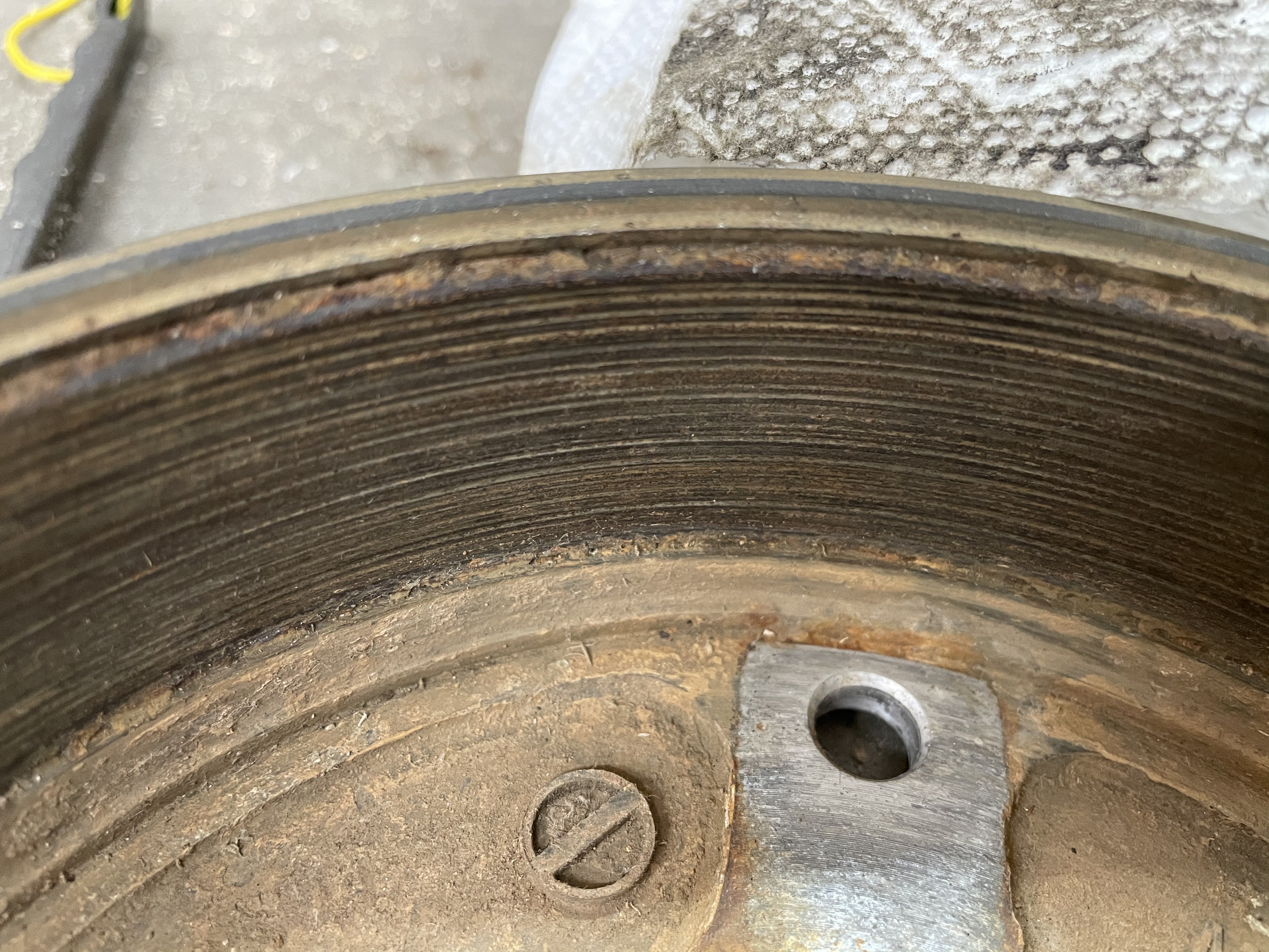
Aside from rust removal the drums needed to be turned on a metal lathe… or in my case; a wood lathe with a four jaw chuck and a square carbide-insert lathe tool. This method worked amazingly for cleaning up the drum. It would be an understatement to say I was surprised and pleased with the results. I was over the moon it actually worked.
Feeling brave from that success, and lacking the patience to wait two weeks for a new part, I secured the self-adjusting mechanism with worn out teeth in a vise and carefully filed new teeth. When I finished filing, the small parts I had soaking in Evaporust were ready to be cleaned and reused.
I read the section on replacing brake pads in the service manual twice to make sure I wouldn’t be taking these apart again anytime soon. I followed the recipe in the manual to a ’T’ even using brake grease in the appropriate locations. Look how clean the springs are now! Fresh pads and clean drums.
And now for the rear drum brake: the compound separated from the pads. The drum surface was still clean and smooth. Drop in new pads and that was it. Effortless compared to the front brakes.
The last step after assembly was a cinch. Flush the brake lines twice and then add fresh DOT 4 fluid and bleed the lines. My test drive a few days later (I hit 40 mph!) was an outstanding success. I smiled the whole time and at the end I was able to stop. The brakes have excellent bite!
1.17.2021 – Sunday
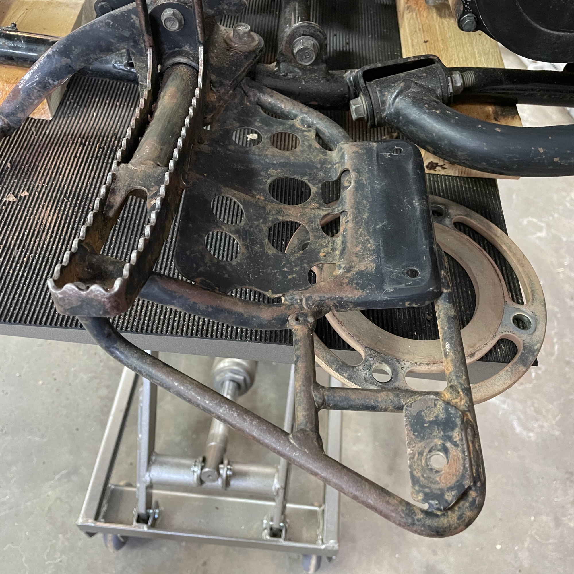
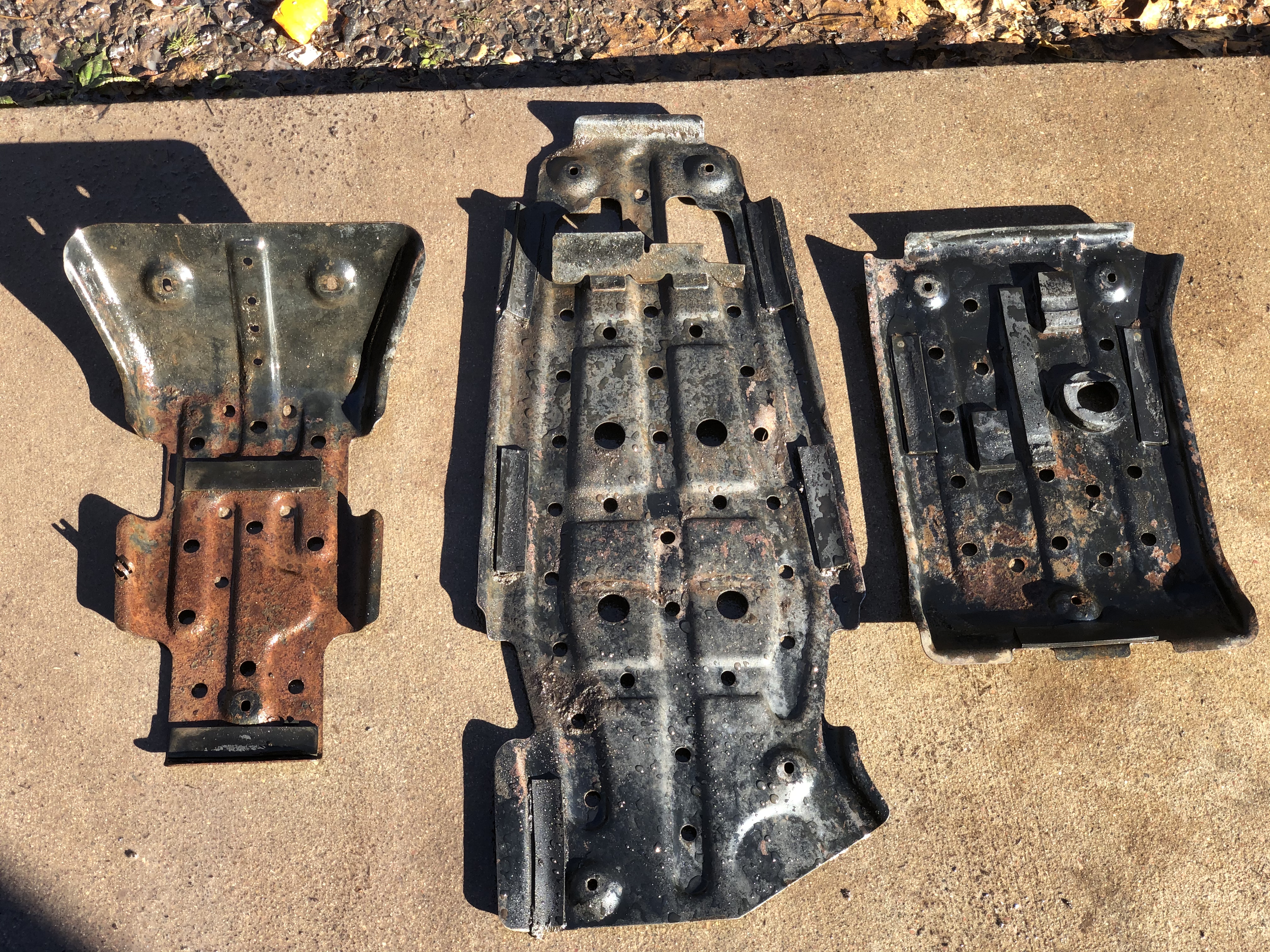
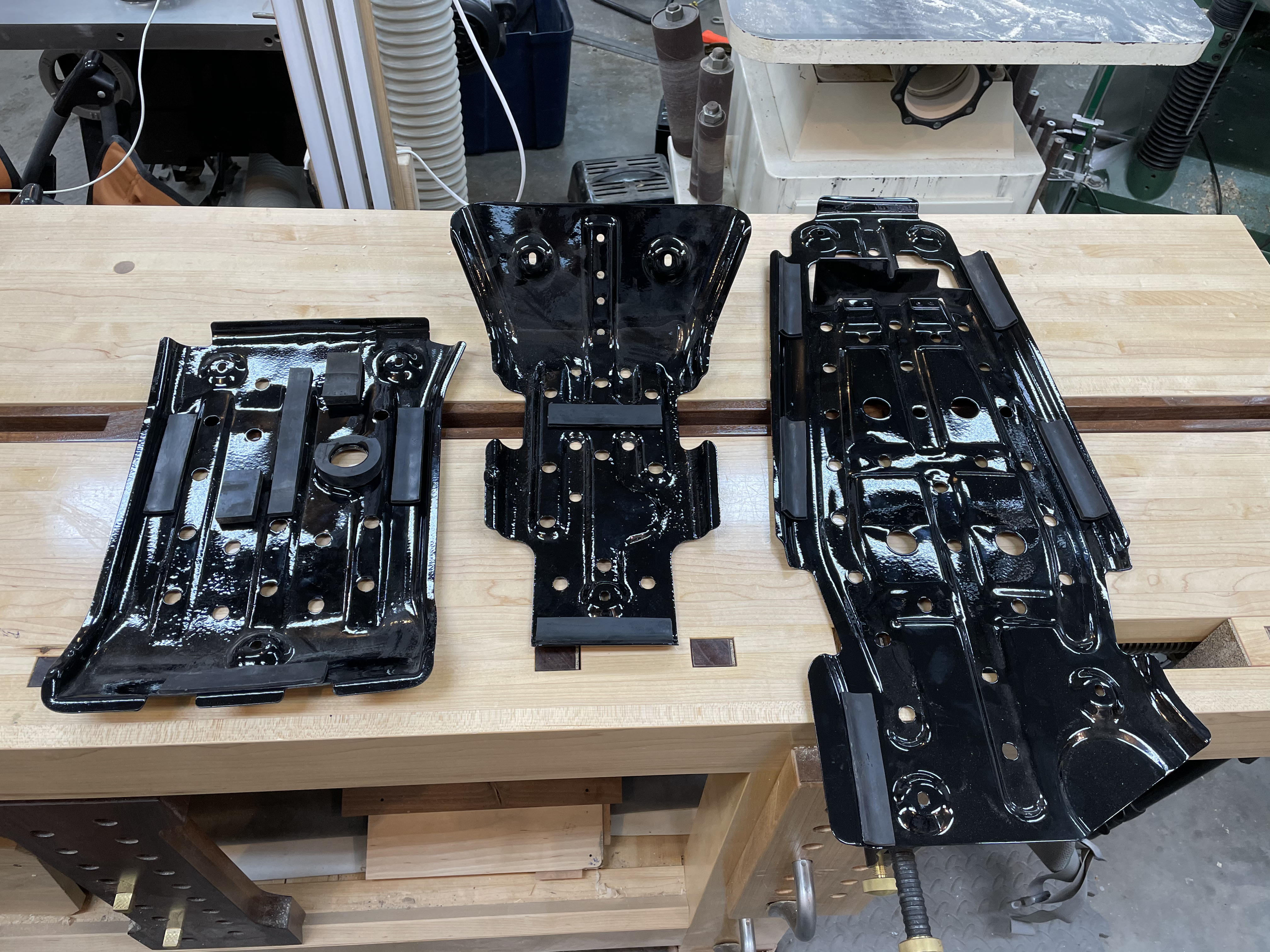
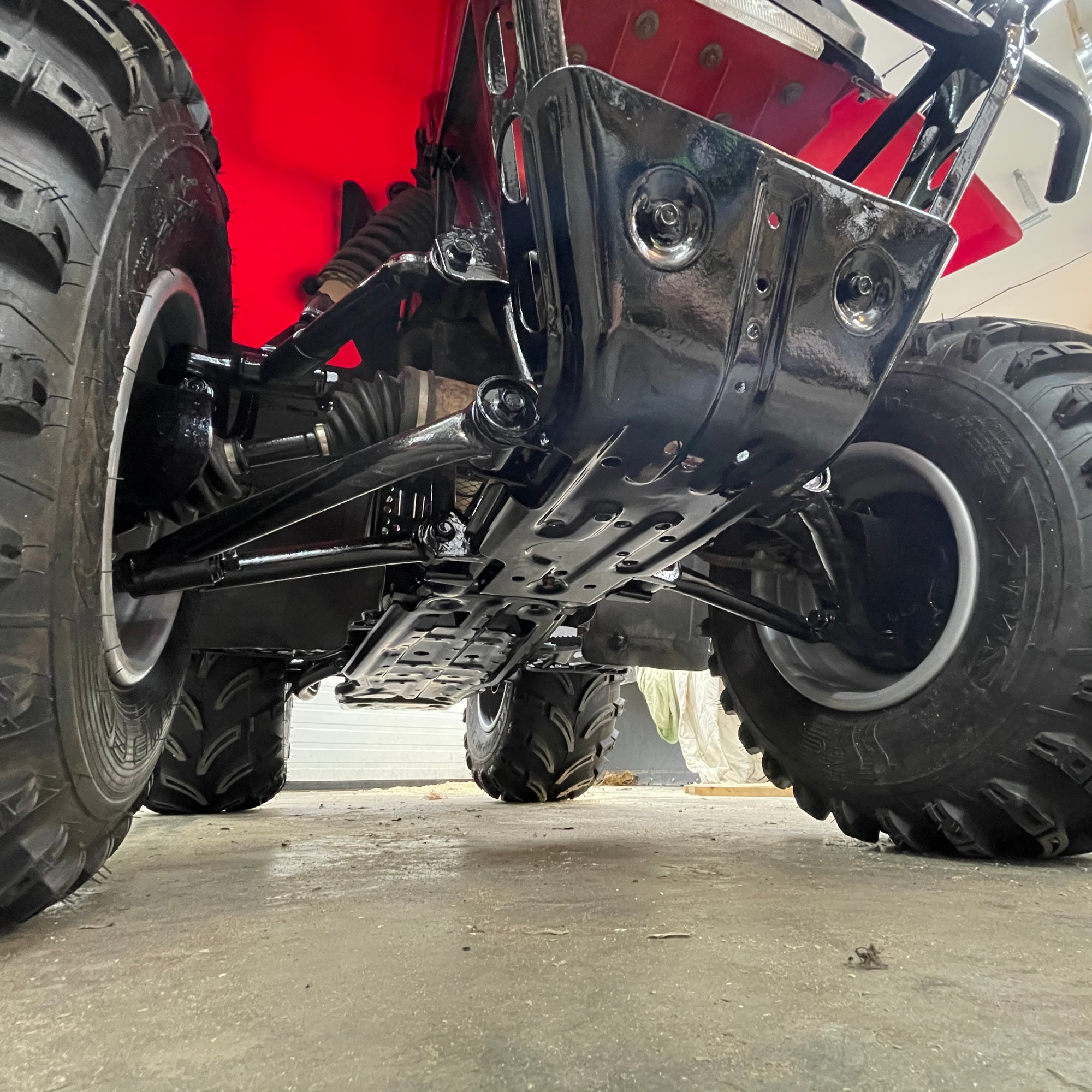
The parts that could be unbolted and given to a professional paint shop were sent off early on. The skid plates had over a dozen rubber pads glued to them to damper and eliminate rattles. Photographs proved invaluable for the reinstallation.
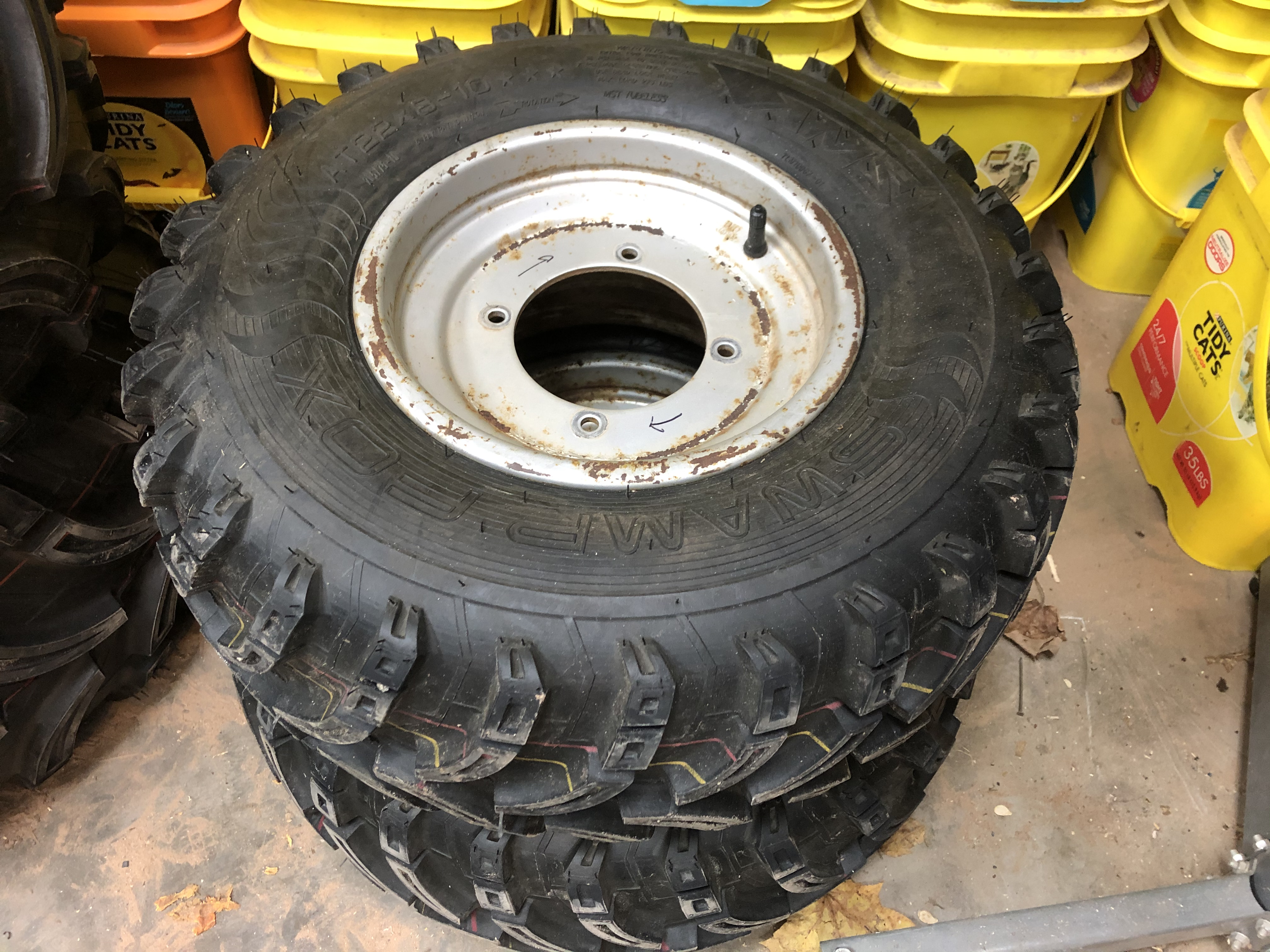
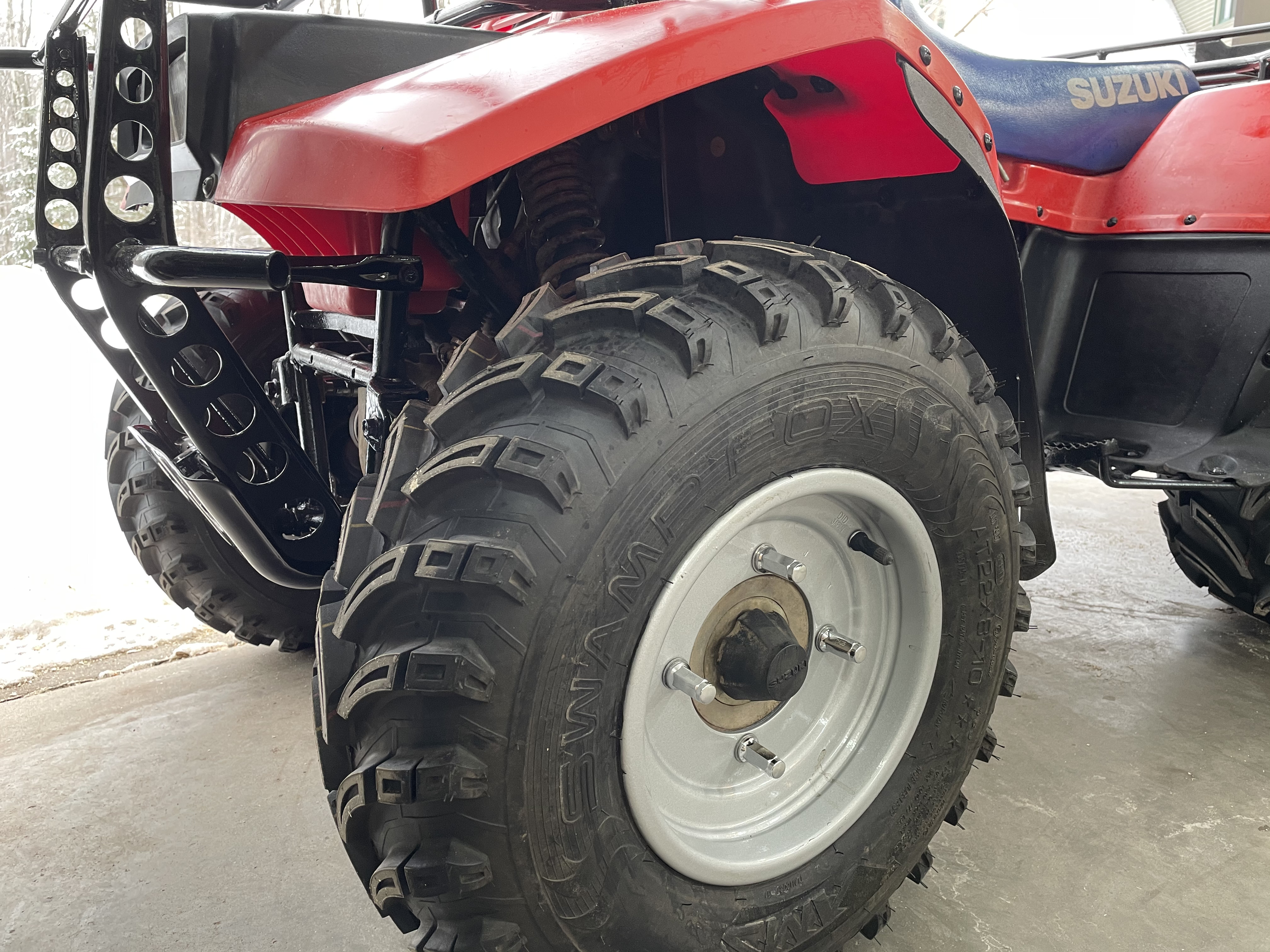
The ATV was acquired with brand new tires. Before encountering engine and battery troubles the previous owner had installed new tires with the plan of keeping this little ATV at their cabin as a run-about. The tires that were freshly mounted were taken off and the wheels sent off for paint.
The front rack had damage and the front most bar was bent beyond my repair skills. The junkyard did not offer up a replacement in bolt-on condition so the rack was sent off to a metal fabricator. The damaged section was cut out and the repair after paint is nearly seamless. As an added benefit, the replacement bar is a bit heavier gauge than stock.
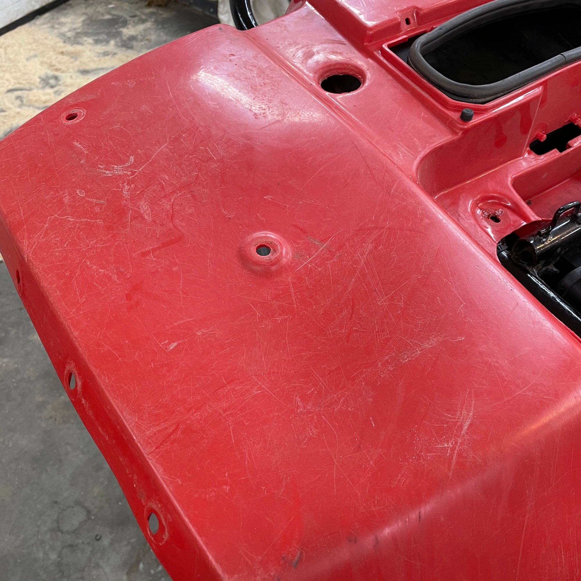
What is the point of fixing up an old ATV and spending $1000 on the project and having ratty old plastic all over the four wheeler?
With the rack off I could easily clean up the plastic.
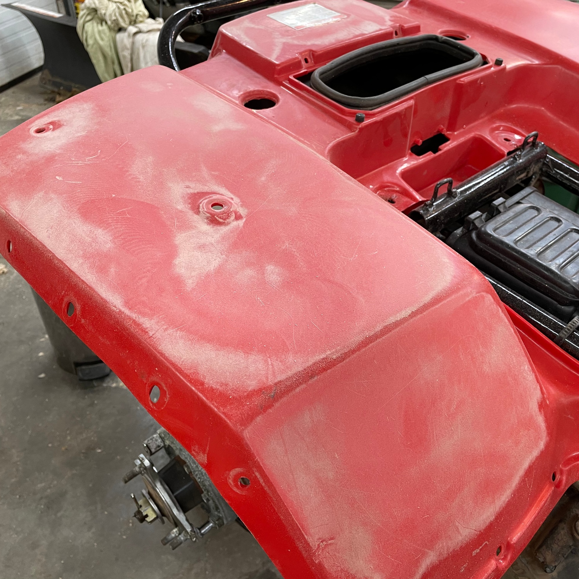
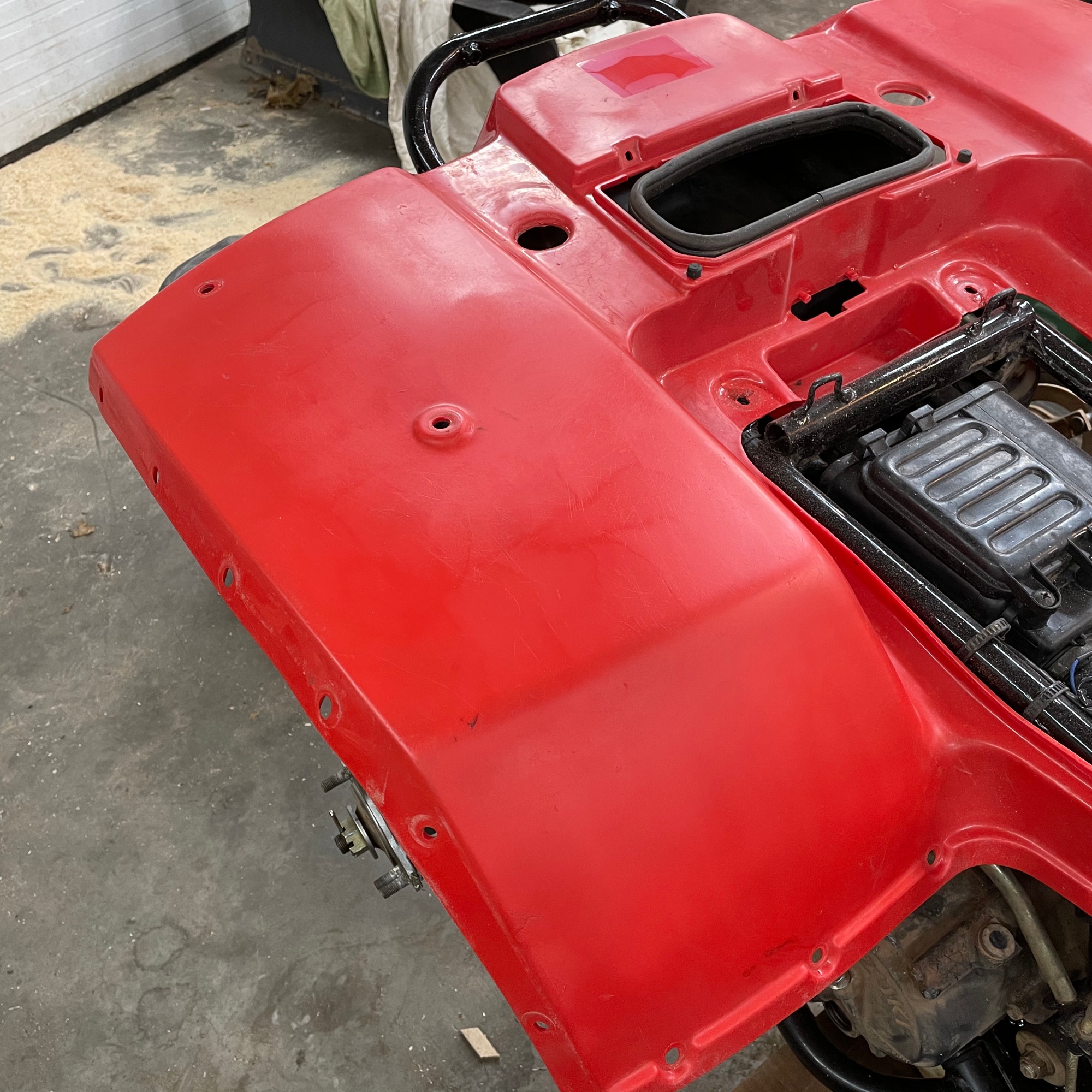
The process was fairly simple. The plastic was sanded with 400 grit on the random orbital sander to remove staining and smooth over small scratches. Once the plastic was sanded uniform the transformation really started to take place.
Using a heat gun on 1100°F the surface plastic was flashed and picked up a nice sheen that is 95% factory fresh. Since the top 0.5mm actually melts, a lot of care needs to be taken to not accidentally touch the heat gun nozzle to the plastic or a hot knife through butter effect will happen and that takes more time to repair.
The oil change was uneventful. It was dirty as expected, but again, no surprises. A new air filter and spark plug were installed at this time too.
1.19.2021 – Tuesday
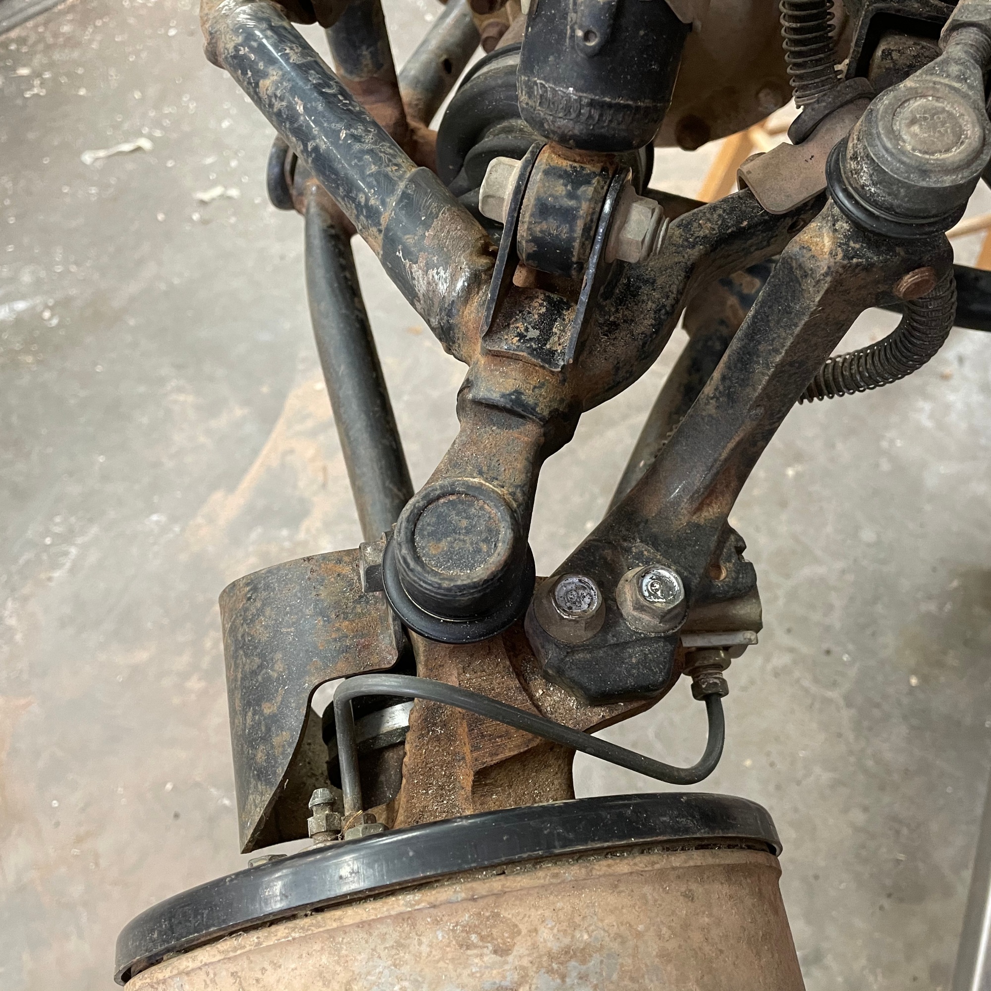
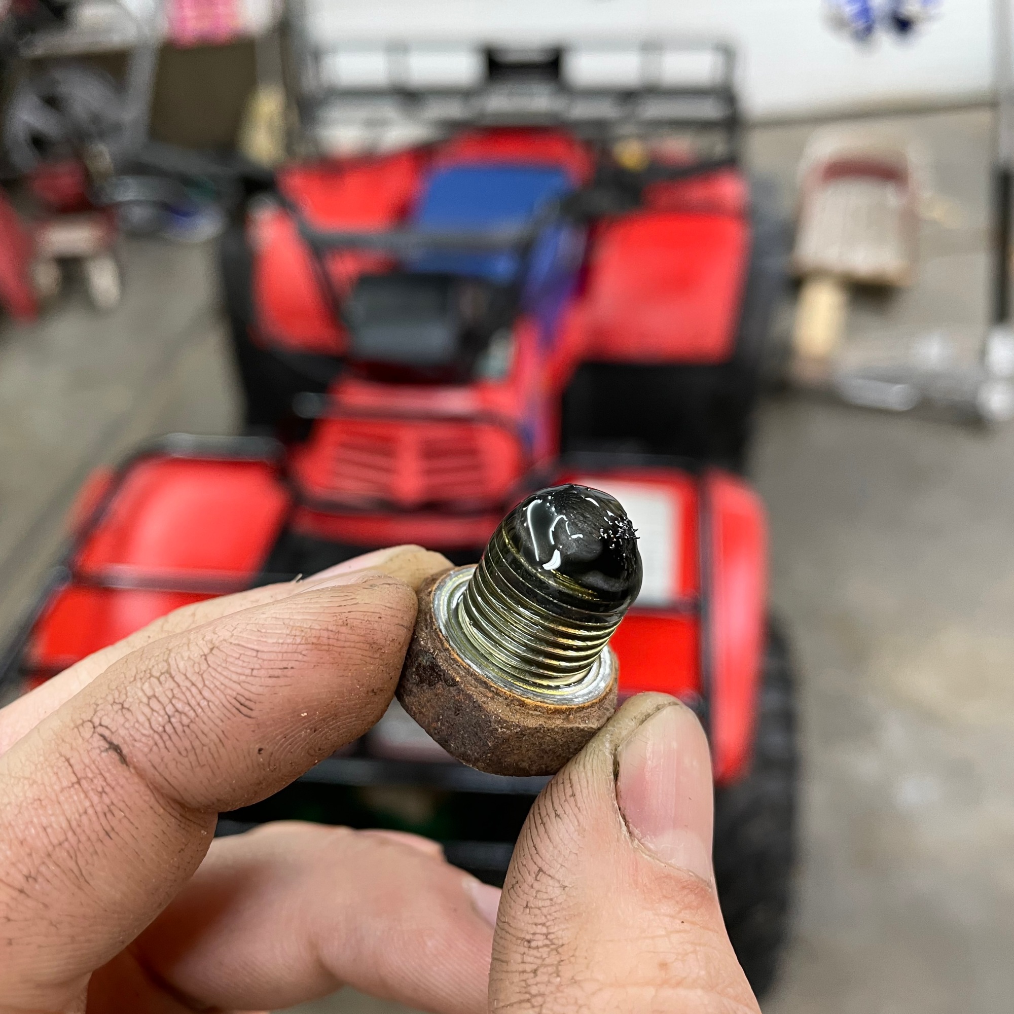
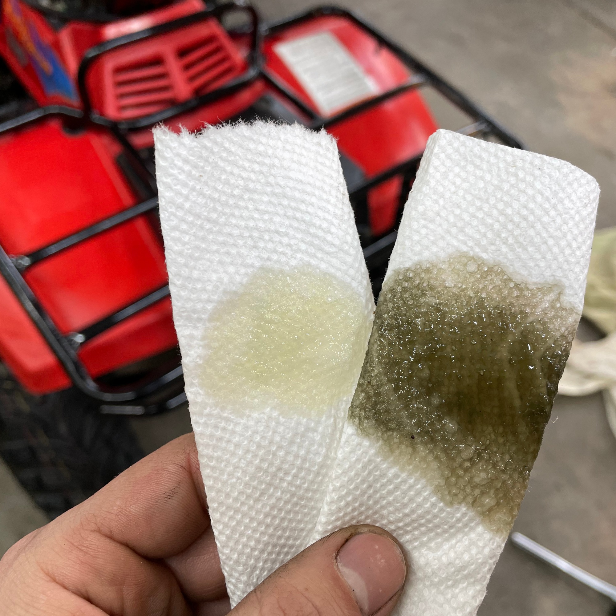
The front differential oil was drained and replaced with Honda GL-5 hypoid gear oil. The Suzuki has a magnet on the differential drain plug (not even my newer 2009 Honda Rubicon has this). The oil was fairly dirty when compared next to the new oil. I also decided to change the fluid in the Honda, which was probably 6 or 7 years old instead of 29 years like the Suzuki (oil samples held in front of each wheeler).
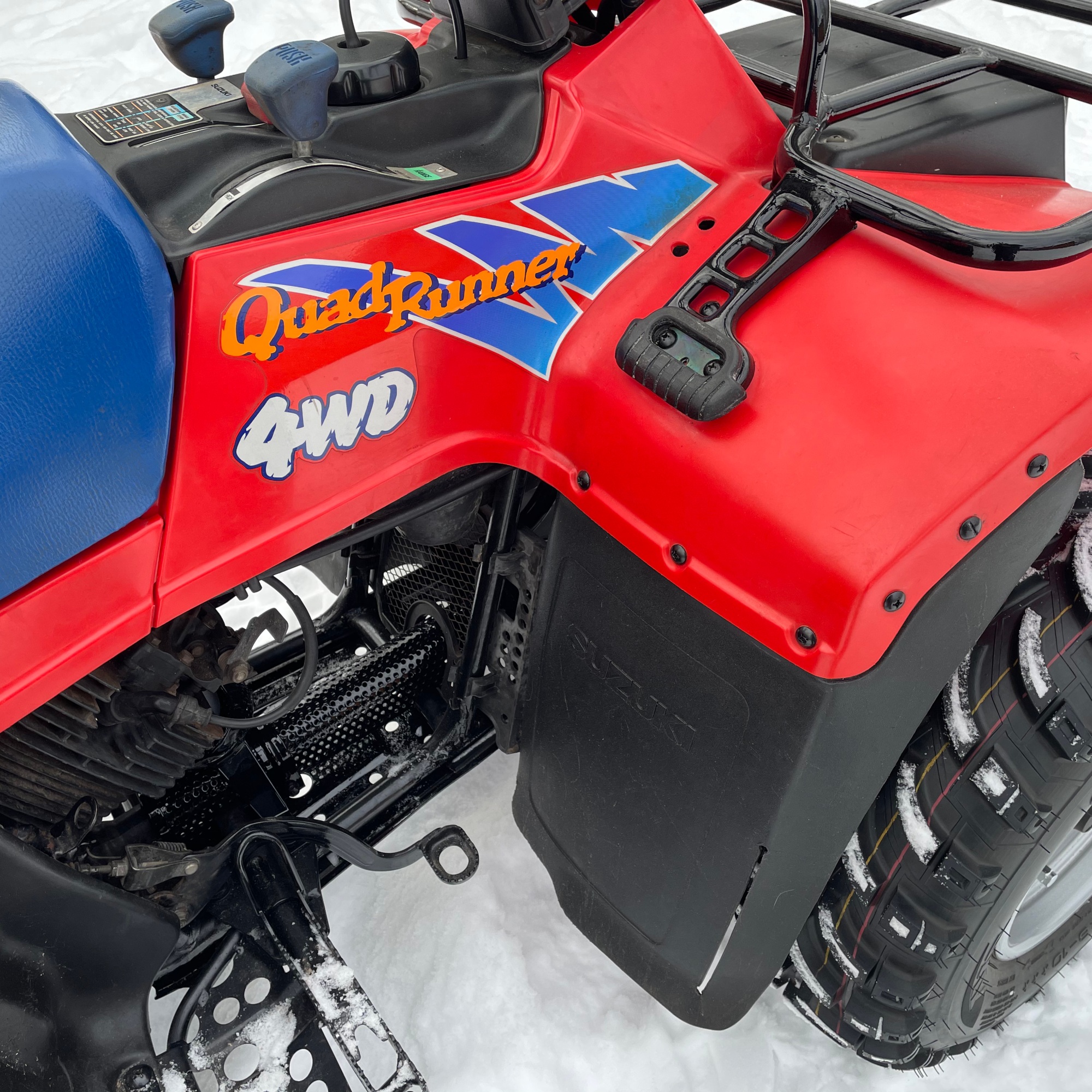
The complex drivetrain has several gear/range selectors under the handlebars. The original rubber dust shrouds deteriorated. In the shop I had some durable siliconized rubber scraps suitable for replacements.
The old rubber was glued on to the metal inserts. It was scraped and then any remaining bits were removed with a small wire wheel on a die grinder. I ran a high quality brad point bit in reverse to cut two holes in the rubber. Then a straight edge and X-Acto knife connected the holes. Contact cement did a fantastic job of securing the new rubber.
After about 15 miles of driving around the homestead and a brief discussion with the Ol’man it was decided that the mirrors should go. I picked up two metric bolts and plugged the holes before touching up the paint a bit.
1.23.2021 – Sunday
The shocks were adjusted to the softest setting on the rear and the second softest on the front to make for a nice comfortable ride. Also, the kiddos will be driving this soon and they are all lightweights; softer is better.
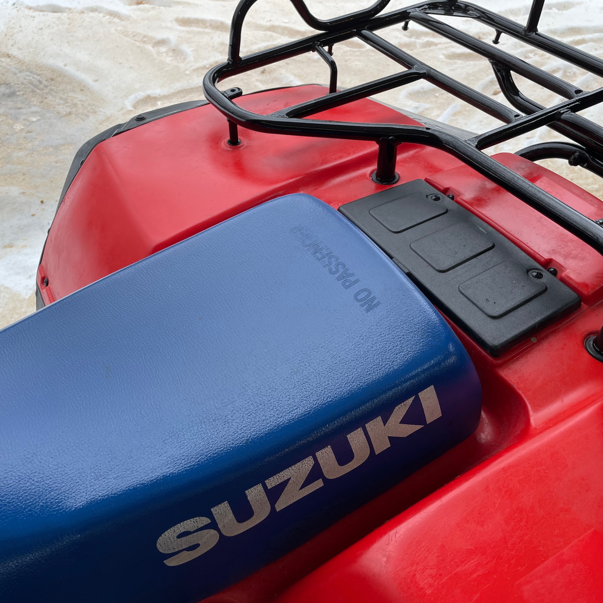
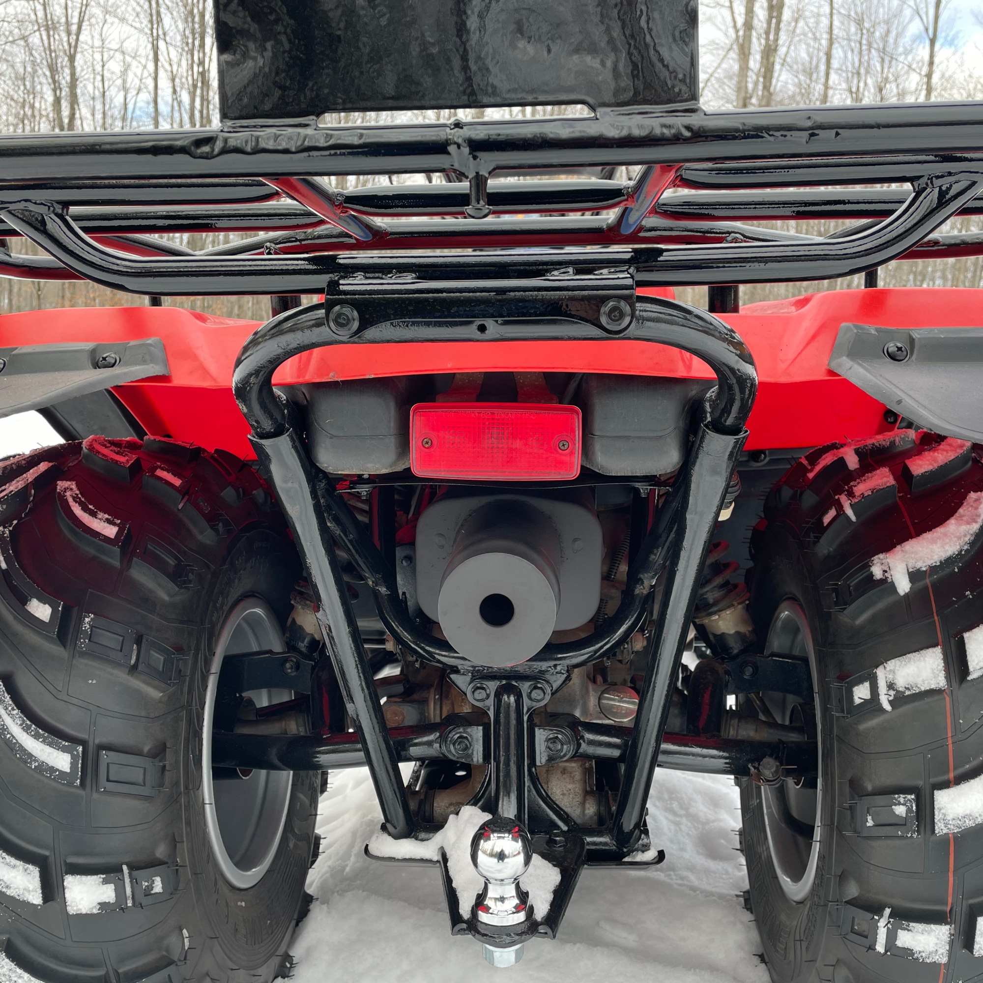
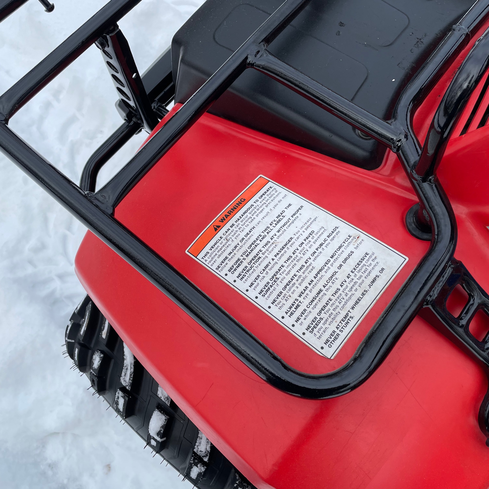
A new foam tube was added to the handle bars and after some debate, the Ol’ man parted with another $50 for new front bumper from a parts warehouse, making the ATV completely restored and original. This is essentially how the quad looked from the factory floor (except for a few missing stickers on the plastic and the upgraded modern tires).
1.26.2021 – Tuesday
The Suzuki is home now! It was just delivered to the cabin and I took the opportunity to snap a photo before heading inside to sit fireside on the couch.
July 2011: the first battery monitor was installed. A Victron BMV-600s.
May 2014: upgraded to a Victron BMV-702
January 2020: added a temperature sensor
January 2020: added a bluetooth module for iOS app compatibility
All along we have had several accuracy issues. The monitor would perform normally for a few hours and then it would be incredibly unreliable. Ultimately, the only useful bit of information it could report was voltage. I pored over the settings and made adjustments, updated software, and even the wiring was checked and redone. No luck.
After over 9 years my long term testing is done and I can say with certainty I would not recommend a Victron battery monitor. The two I still have aren’t for sale (or free for that matter) because I can’t in good conscious give away an inferior product that I wouldn’t use myself.
In this new post-Victron battery monitor world the Ol’man and I tried something new: a pair of generic battery monitors. The model I selected is the bayite DC 6.5-100V 0-100A LCD Display Digital Current Voltage Power Energy Meter Multimeter Ammeter Voltmeter with 100A Current Shunt from amazon.com
Specifications:
Working voltage: DC 6.5 ~ 100V
Measuring Accuracy: 1%
Power Consumption: 0.2W
Measurement speed: 2 times/s
The blue backlight can be turned on/off manually
Test Range and Display format:
Active Power range: 0~10kW
Energy range: 0~9999kWh
Voltage range: DC 6.5~100V
Current range: 0~ 100A
Pretty basic specs. I purchased two and installed them in the garage. The are affixed to the wall with that really awesome outdoor velcro made by 3M that goes by the trade name: Dual Lock Reclosable Fastener.
The top monitor records information for the 12V accessory system at the cabin (cellular booster, 12V motion lights, cabin phone charging station) and the bottom records the solar energy generated from our 810 Watts of PV array. So far after half a year of use, these two $16 monitors have proven accurate and reliable. One advantage, and something the Ol’man and I both took a liking to is the ability to see four values at one time; Volts, Amps, Watts, and Watt hours. With our previous battery monitor, only one value was visible, and manual input via a tiny stiff button was required to glimpse additional values. Here is the full user manual for these two garage battery monitors.
With the success of the two new monitors in the garage my attention was turned toward the cabin. The search for a Victron upgrade began and ended in about 30 minutes. The clear winner was a unit from Renogy and it came in around a reasonable $100. It has a much shorter User Manual than the Victron and displays all the important information at once. Specifications:
The wiring was a bit of a challenge and took about 3 hours to test and verify. I was sure glad I brought a multimeter to the cabin to test continuity or else I would have gone mad. The solid core ethernet cable could be stripped and inserted in to the five pin connector. The fit was good and once shrink tube was applied over the connection it produced a sound cable. I built several cables this way.
The 5-pin to ethernet adapter cables allowed the existing buried ethernet cable to be used for the new monitor. The original layout and design of the system allowed for these additions to be easily integrated.
The screen is intuitive and displays a lot of information at a glance. The bottom of the screen shows voltage, amps, watts. The time on the right side can mean one of two values depending on the battery icon: time to full charge or time until battery depleted. The battery icon has two small triangles that will point up if the batteries are being charged, or down if the battery is being under draw.
But wait! There is one more thing! Because the display shows all this information at a glance and we have wifi connected surveillance at the cabin, remote monitoring of the off grid system is now possible.
The camera holder simple and adjustable. It is just three elm boards drilled and threaded for 3/8″ rod with slots cut in two for adjustability. The boards are finished in shellac with self adhesive cork applied on the surfaces that contact the half wall.
Below is an image from the Blink camera. The camera is positioned at the correct distance for the auto exposure to adjust to the backlight and produce an easily readable image.
After a month of service it was decided the Renogy is here to stay. The temporary faceplate I made was discarded and the battery monitor was carefully hand fit into the wall.
There have been a few small things that have bothered me and the Ol’ man. This year we fixed five of them.
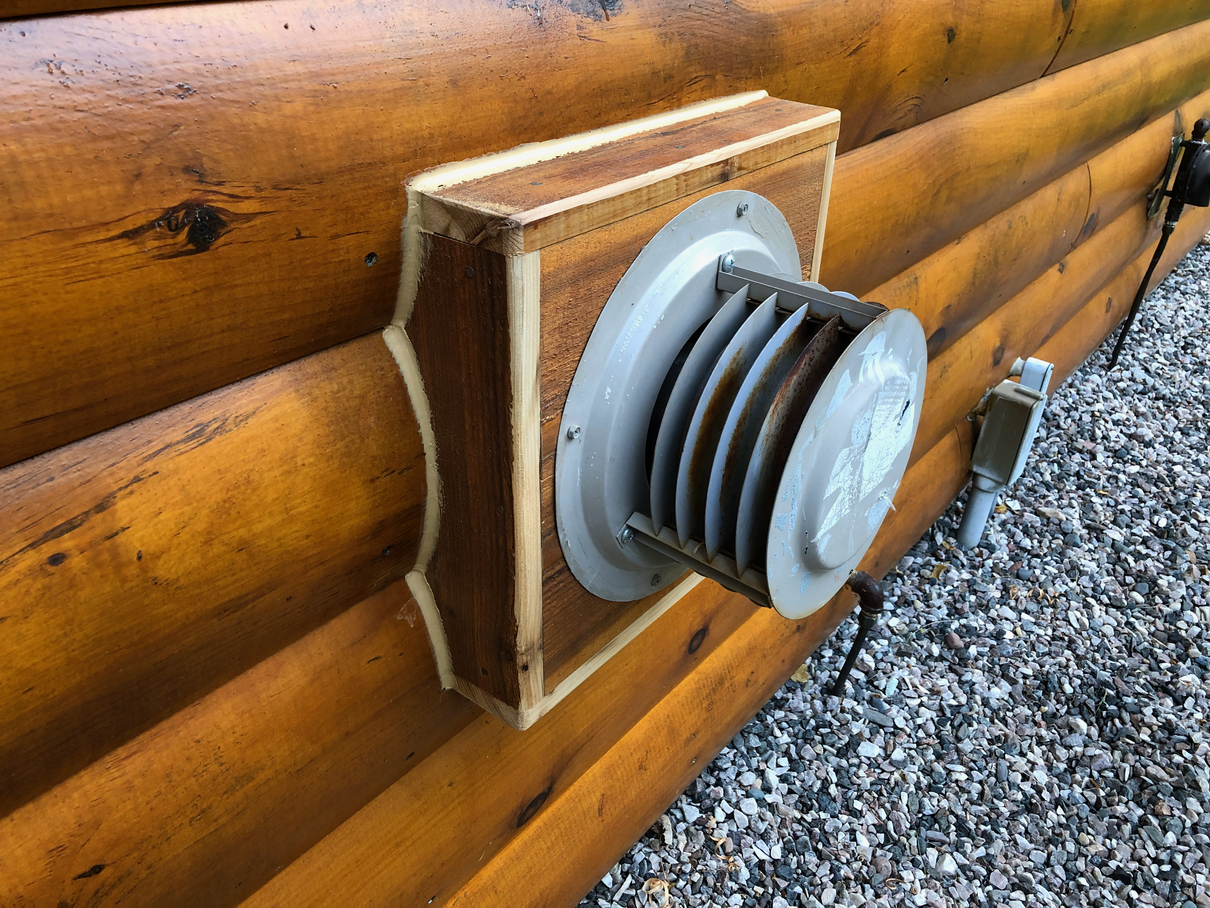
The longest standing, and first to be fixed, has bothered me since day one. The garage has a simple wall mounted propane heater on the inside. We keep the pilot light off and use it maybe twice a year during the cold months. The past few times it’s been run has been for our convenience when cutting up a deer. It’s become a sort of best practice that the Ol’ man and I usually have a deer quartered, deboned, and in the fridge within 6 hours of shooting. Despite the infrequency of use, the vent to the outside is often seen, and in my case, noticed.
The Ol’ man had some left over rough sawn pine from the Cabin construction (of coarse). He pre-finished it and I brought some wood working tools up to the cabin on July 6, 2019. The installation was very simple. I clad the existing OSB box with the pine and broke the corners with a block plane. Later, some additional exterior finish was applied to darken the fresh wood revealed by the block plane.
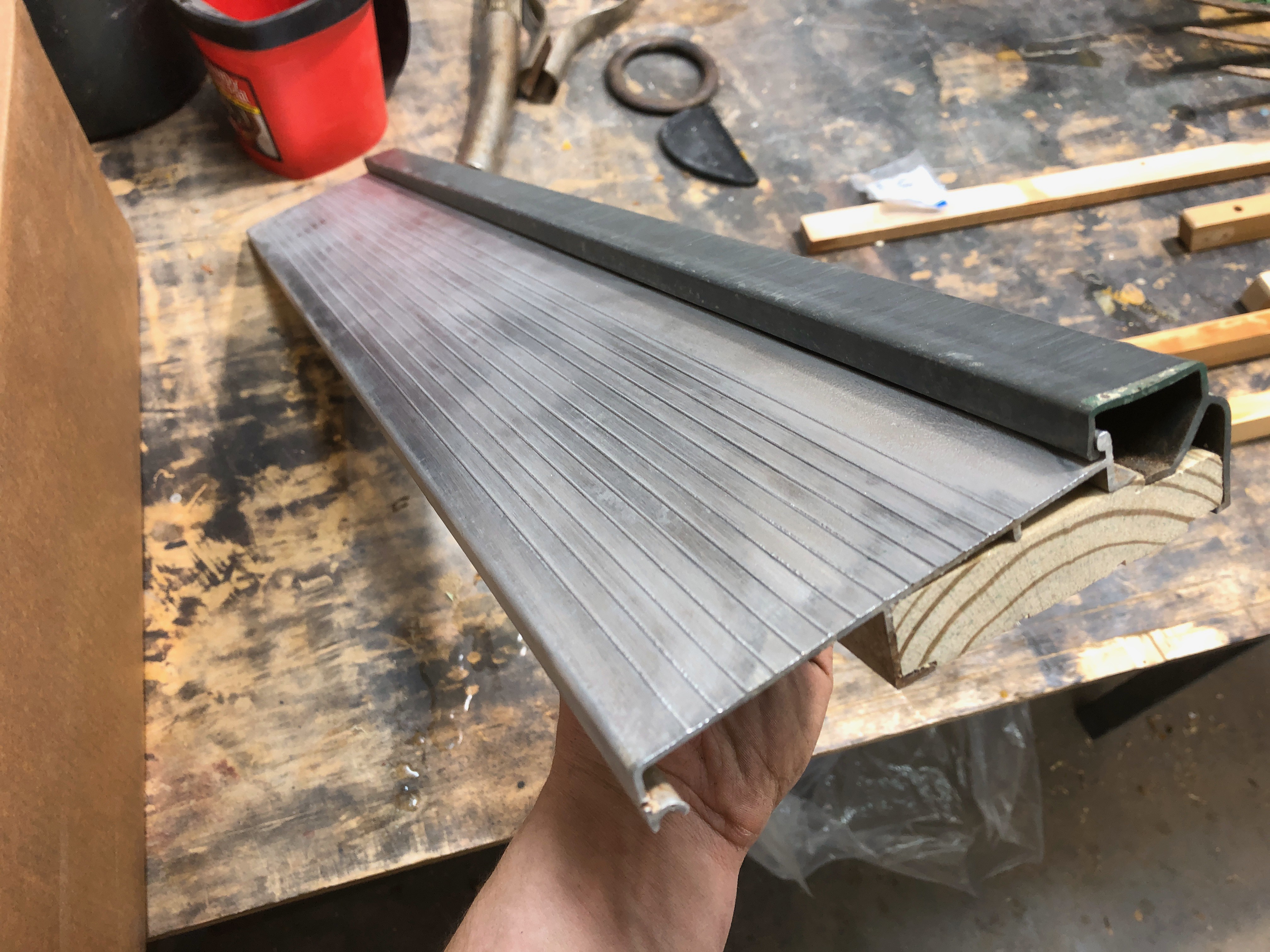
The next two improvements were required. They were finished on July 12, 2019. From use and the elements a bit of wear and tear was suffered by the garage service door sill and our porch railings. The sill was taken back to my shop and cleaned up with a wire wheel on an angle grinder. The rotted wood was replaced by a new version carefully milled from treated pine. This time we used concrete screws and a carefully selected multi-surface construction adhesive to secure the sill to the slab. Previously, water had run under the sill into the garage. That won’t be the case this winter.
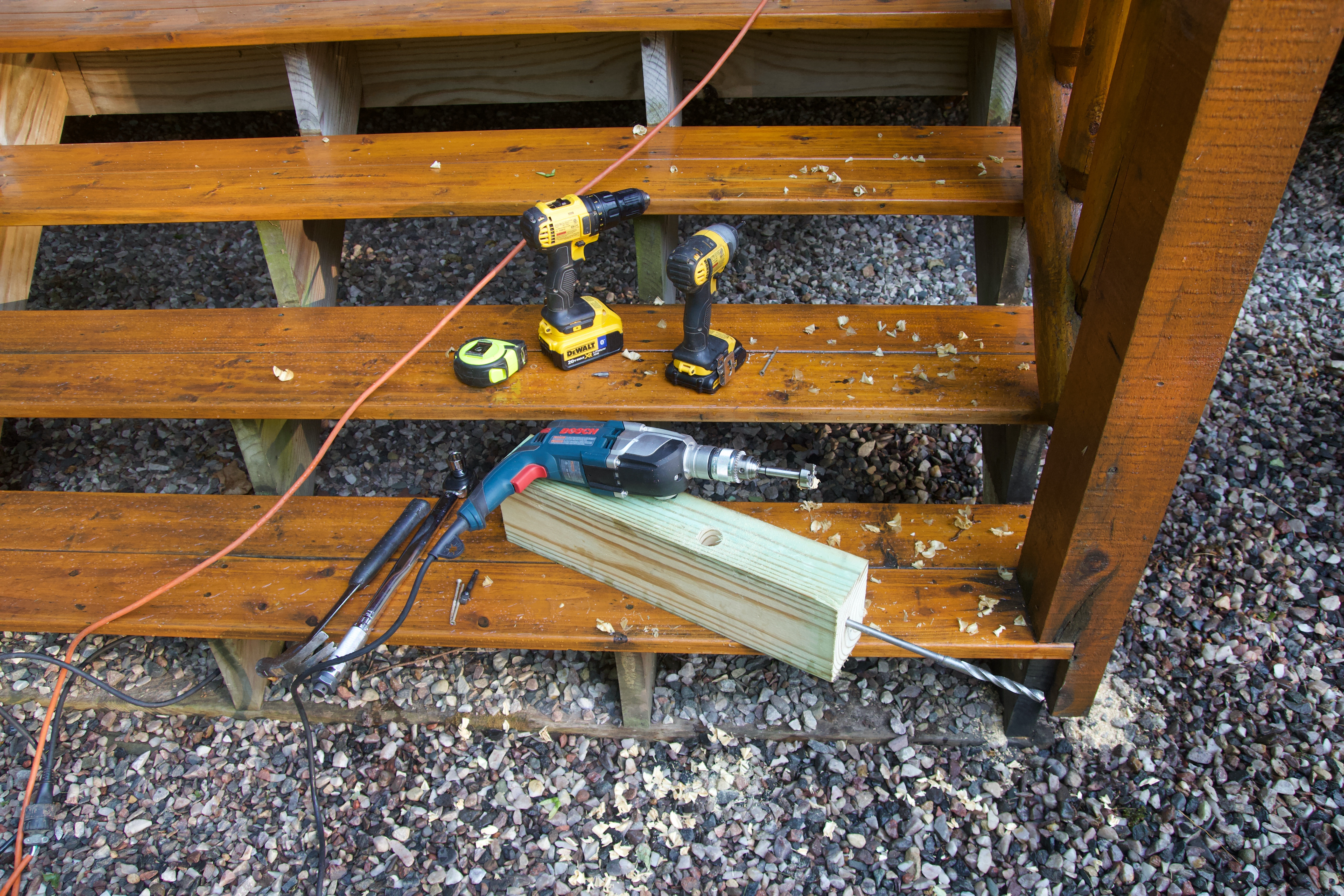
After a quick installation of the sill we moved on to the biggest improvement. The bottom post on all three outside stairways has always been less than satisfactory. They would wobble and inspired little confidence in their permanence if you leaned on them. My investigation into a fix began a few months earlier. I had just built two Shaker Low Post beds for my house in the wood shop and found the solution in their construction. The beds featured captured nuts and heavy bed bolts to secure the posts to the rails. I wandered around Menards for a while after work one evening and found the necessary parts for the project. In late May I began to prepare my materials for installation.
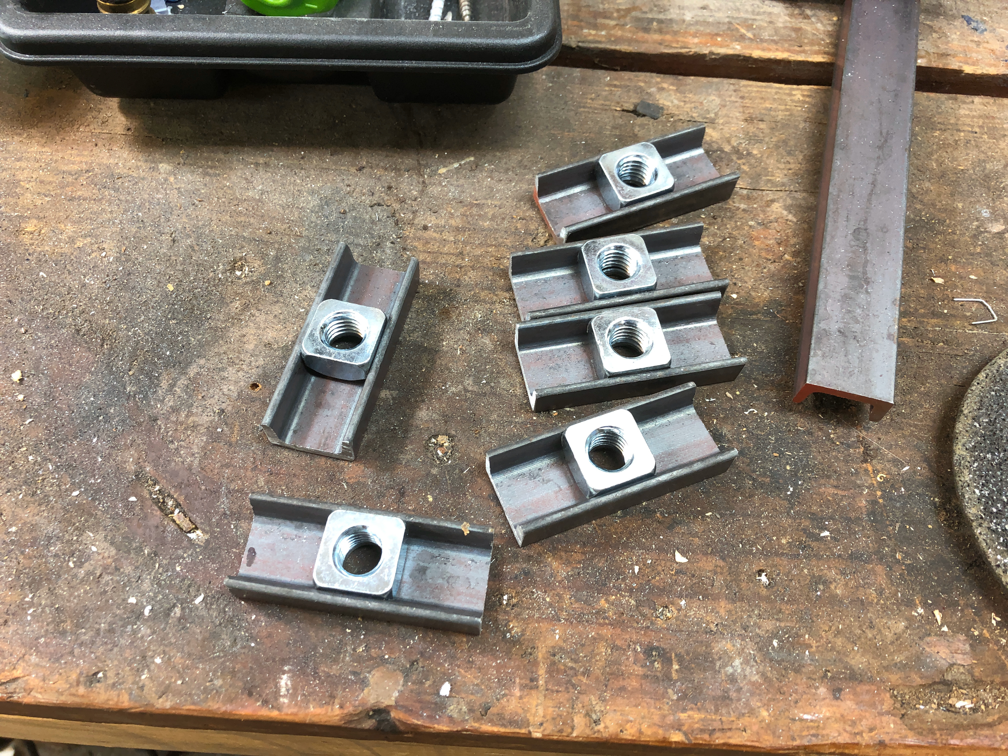
I cut a long C-channel bar into shorter lengths and ground two shoulders of the square nuts to fit.
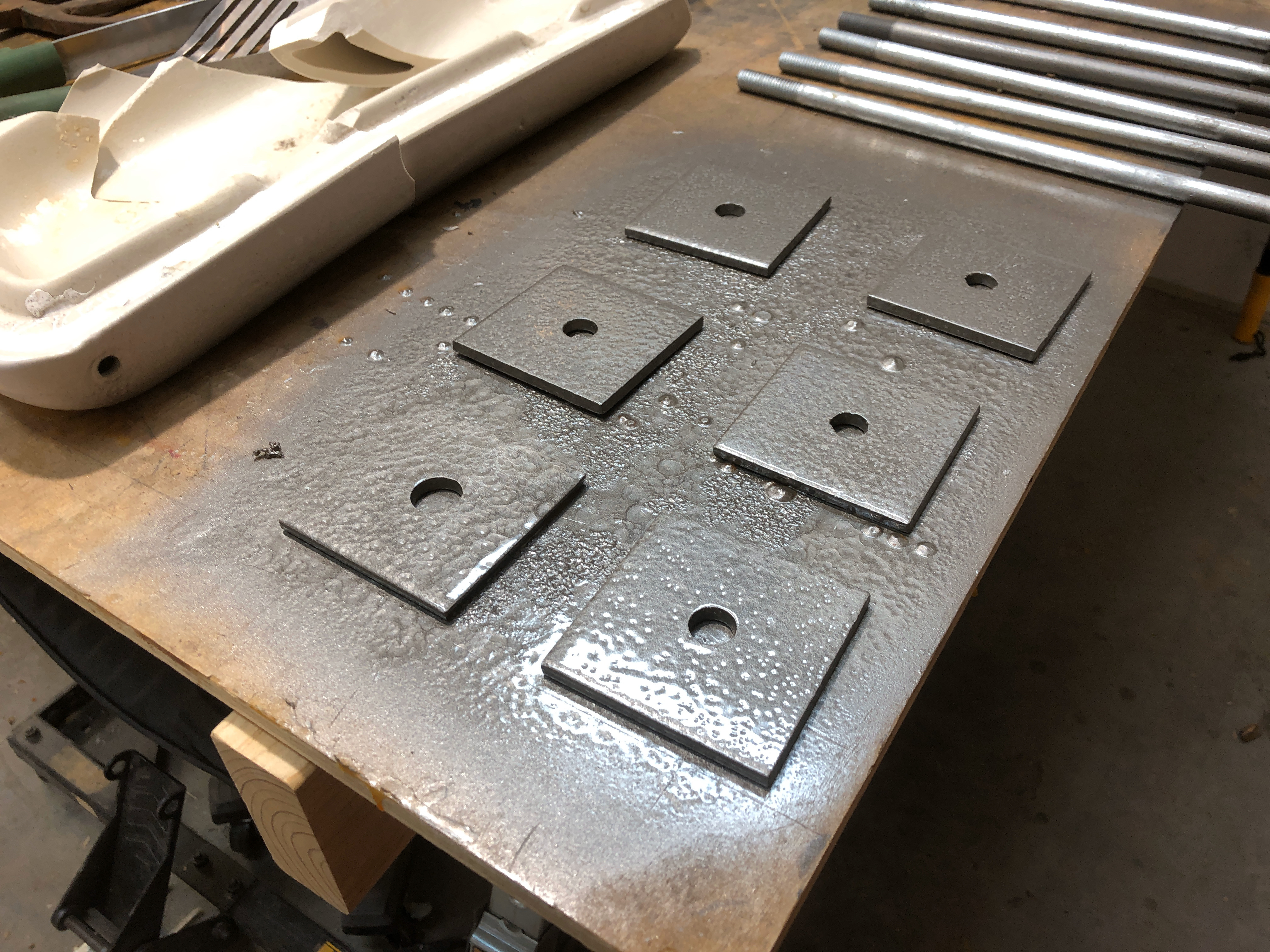
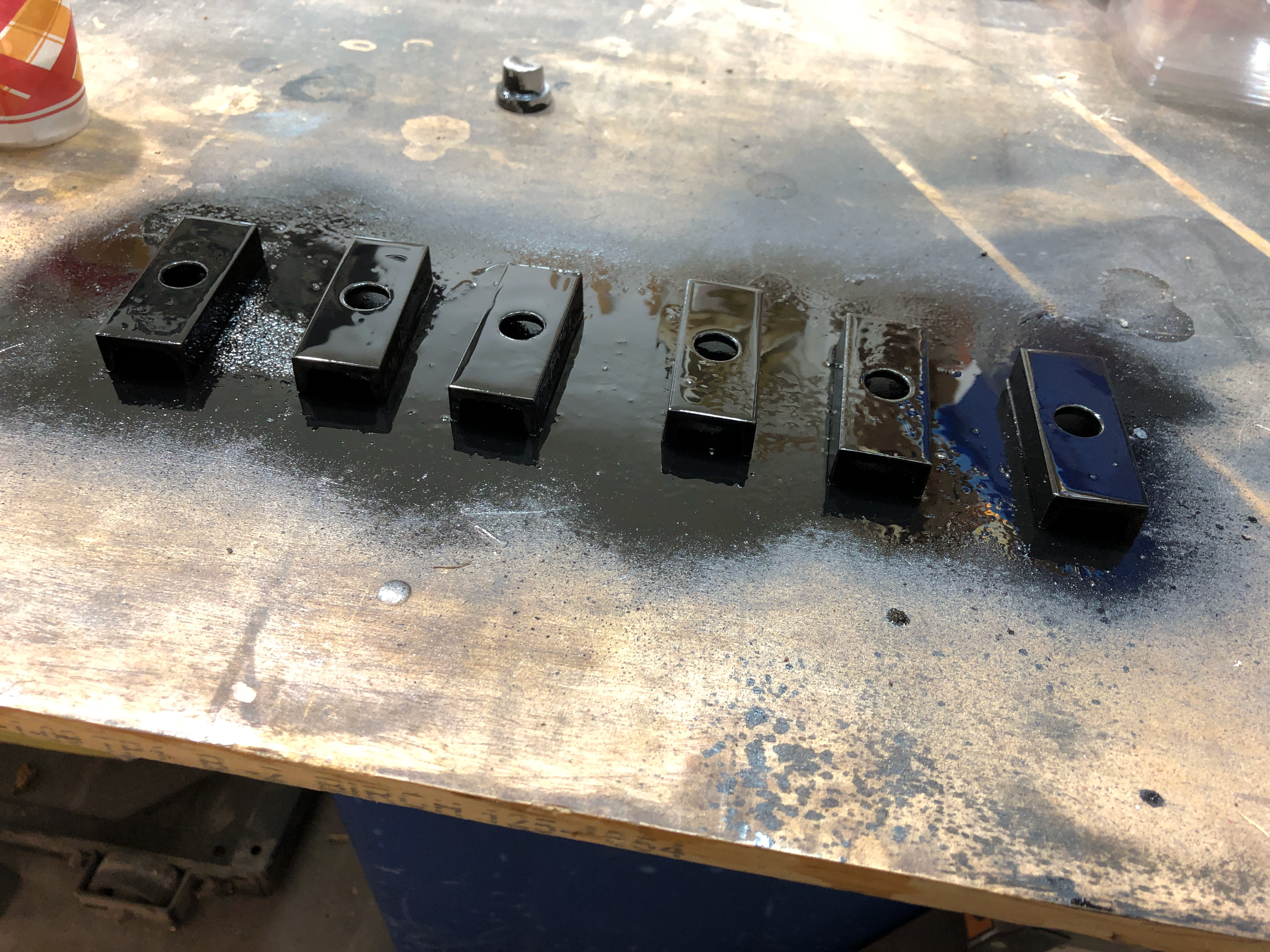
The thick hot dipped galvanized square bearing plates got a nice coat of dark bronze hammered paint. So did the bolt heads.
Because the steel will be in contact with treated wood I cleaned them and appleid a thick coat of paint to the C-channel.
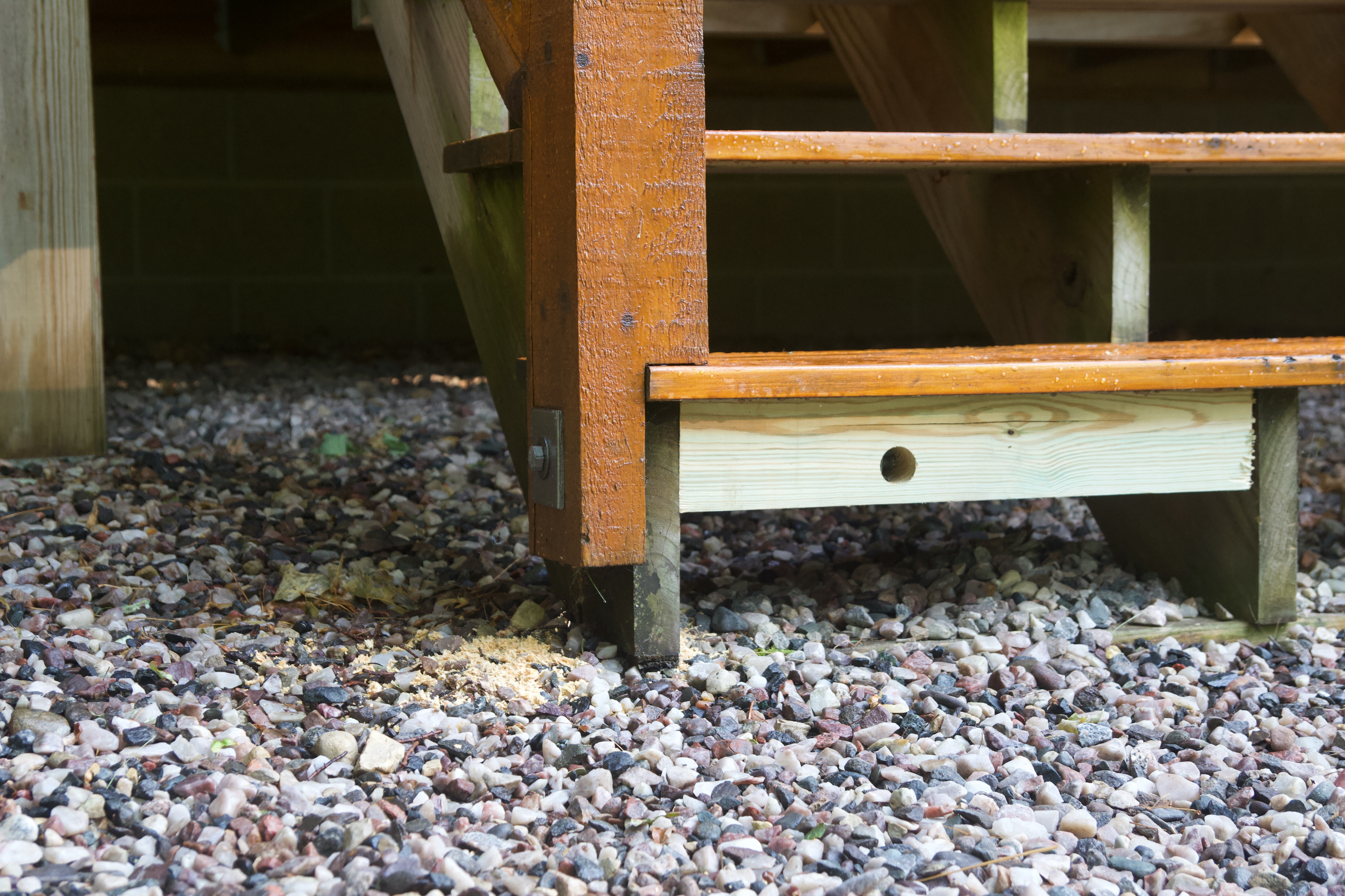
Installation of the captured nut and bolts was straight forward. A block of treated 4×6 pine was cut to fit snug between two stair stringers. Next I clamped it in place and drilled a long hole for the bolt. The block was then unclamped and using the first drill bit as a quick guide to double check my aim, I drilled the hole for the captured nut.
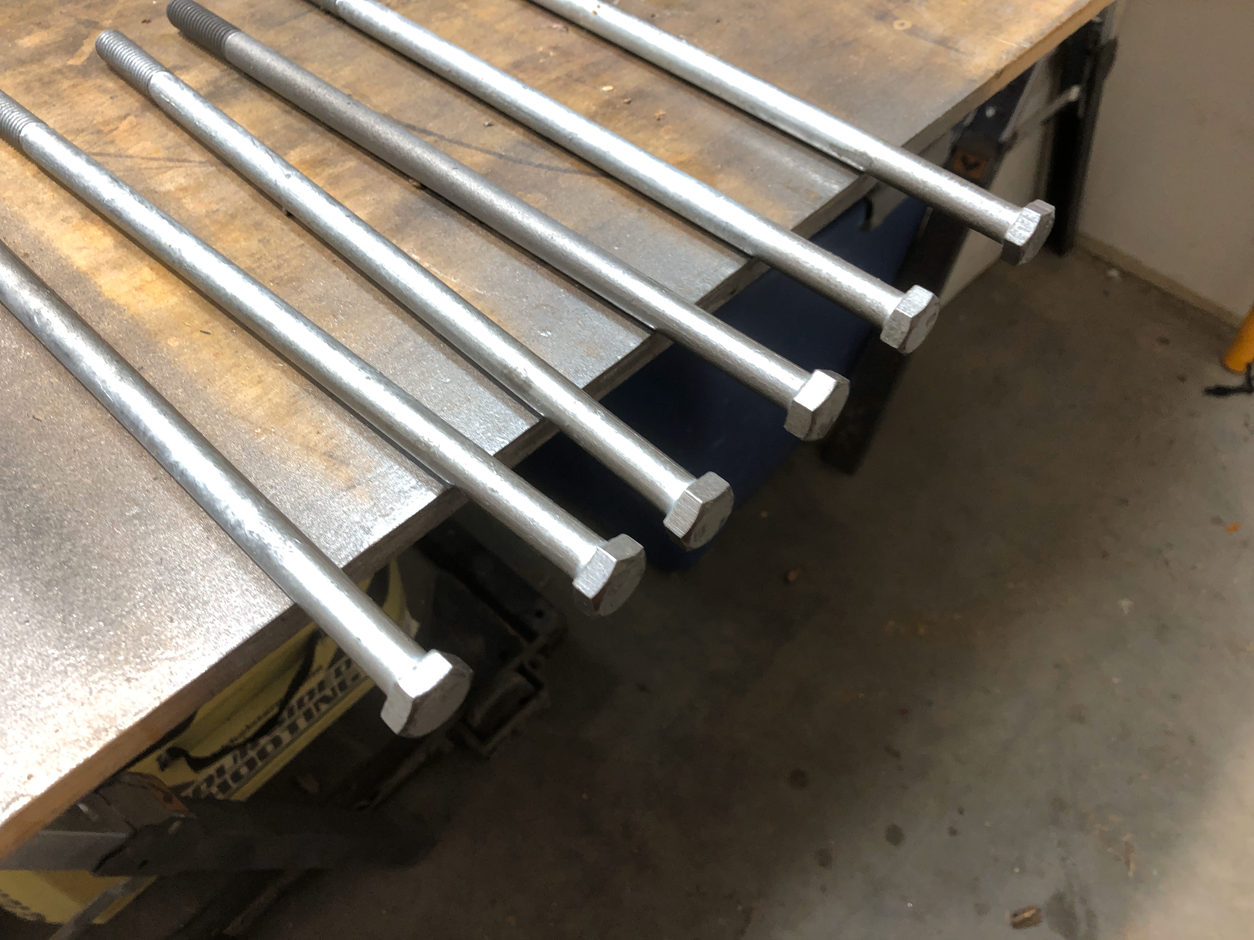
The 12” bolt is 1/2”-13TPI galvanized with a 3”x3” sill plate for contact on the post. It is installed exactly like a bed bolt, but the design has a 1” steel C-channel piece of steel about 2” long that cradles the square-nut. Tightened to 86 ft pounds the clamping power should approach 9,000 pounds. The rail gained incredible rigidity compared to before.
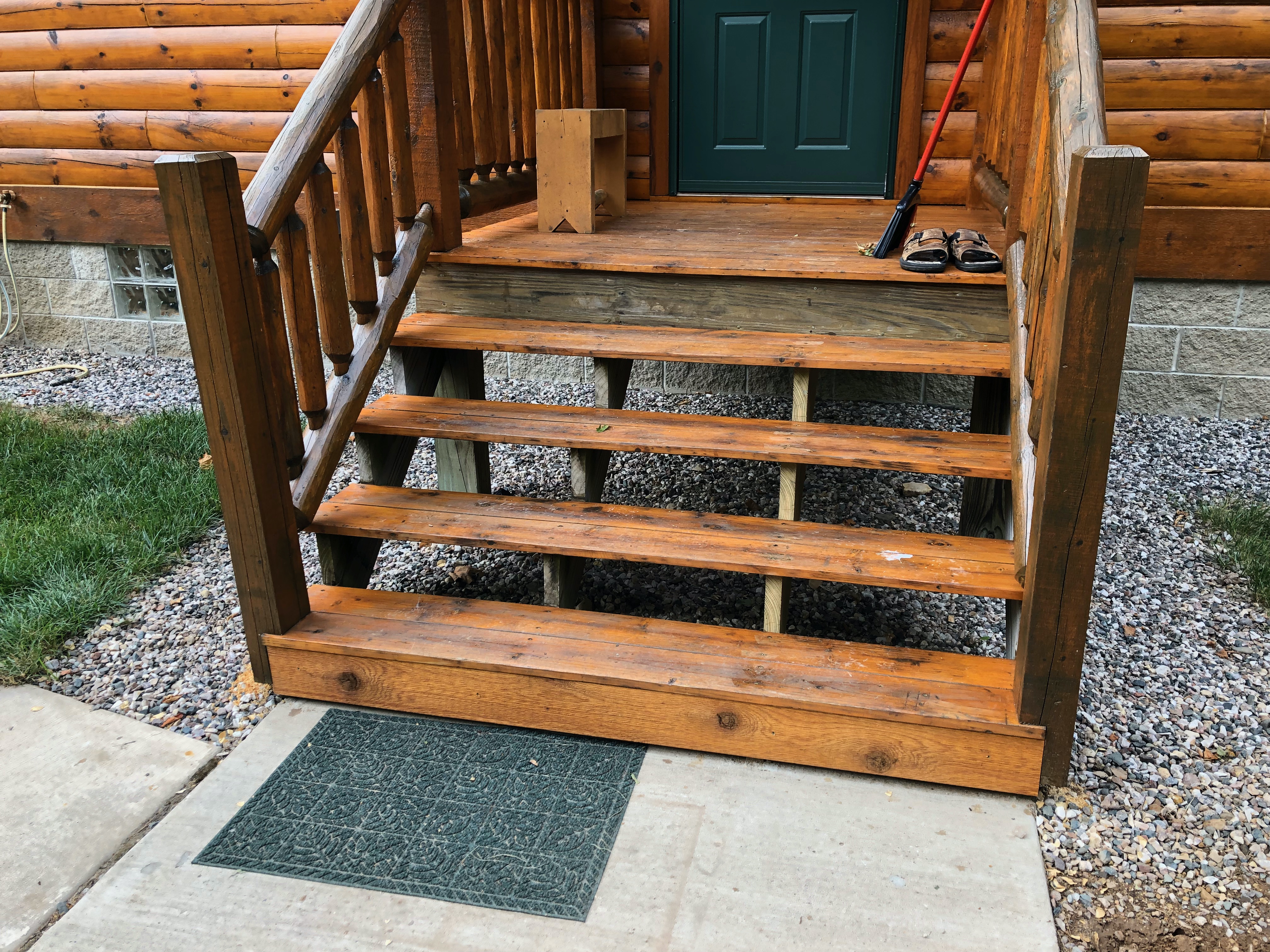
Look close and you will see a new stair stringer in the photo below. The previous one was split from deck screws placed too close to the front edge. The front of the stair tread us left unsupported by the damaged stringer and bent down with weight. We also replaced that when fixing the posts. That was a simple task of removing the old stringer, copying it, and installing the replacement. Later, the Ol’ man returned with some pre-finished rough sawn pine and dressed up the repair. We are now contemplating dressing all the stairs with rough sawn kickers.
We uncovered a future repair project while reinforcing the posts. Off the front porch the posts were in contact with the ground. The bottoms rotted out and can’t be saved. The two outside treated stringers will also need to be replaced. This is a project for 2020. The Ol’ man already had two sets of pine posts cut from our local mill this Summer and treated pine stringers are just 2×10’s cut to fit.
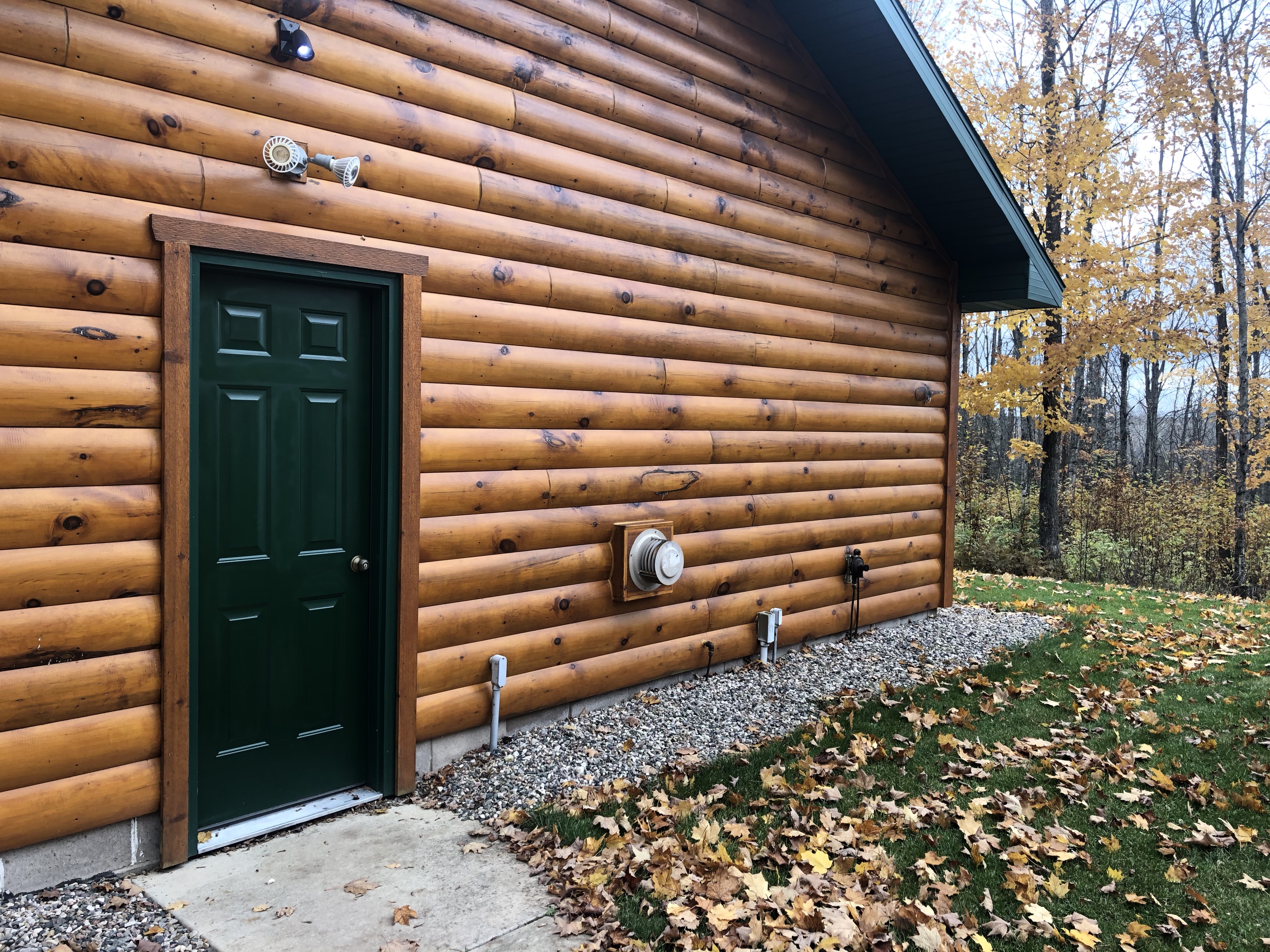
In mid-summer the Ol’ man put that final coat of paint on the garage service door. He also refreshed the trim. Before this, the door was lighter green than the cabin doors and the paint was streaked with brush marks and a paint that didn’t fully cover the primer. The door is now deep green and looks so good. It took 10 years, but it finally matches the cabin.
The final project was finished up on the second day of the Michigan gun deer season. I was held up from making opening day at the cabin. Something about being a good husband and watching the three kiddos while my wife attended some sort of Women’s night thing in Marquette. Yeah… I don’t get it either.
I made due and hunted the opening from my second floor study at home. Life is a compromise sometimes. This was a fine compromise.
I planned to arrive at the cabin by noon, but as you can see, I had a late start. I didn’t make it to the cabin until 1:30pm CST on November 15, 2019. Most of my time at the cabin this deer season was my attempt to combine the irresponsibility of Octoberfest with the gluttony of Thanksgiving. Fitting I suppose since it falls between the two on the calendar. I took a break from my gastrointestinal cross training to do the final cabin upgrade of this post.
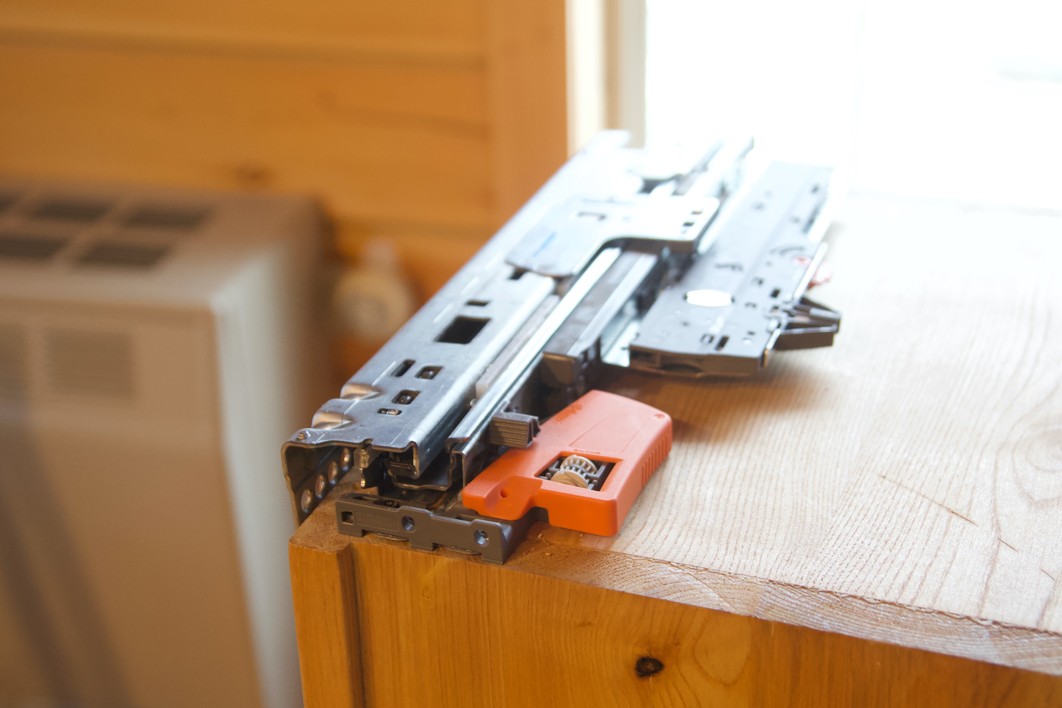
After recovering from the events of the day (and night) before I skipped the morning hunt and started on the upgrade to the garbage drawer in the kitchen. I purchased the fanciest drawer slides I could find from LeeValley.com two weeks earlier. Now I had to figure out how they worked.
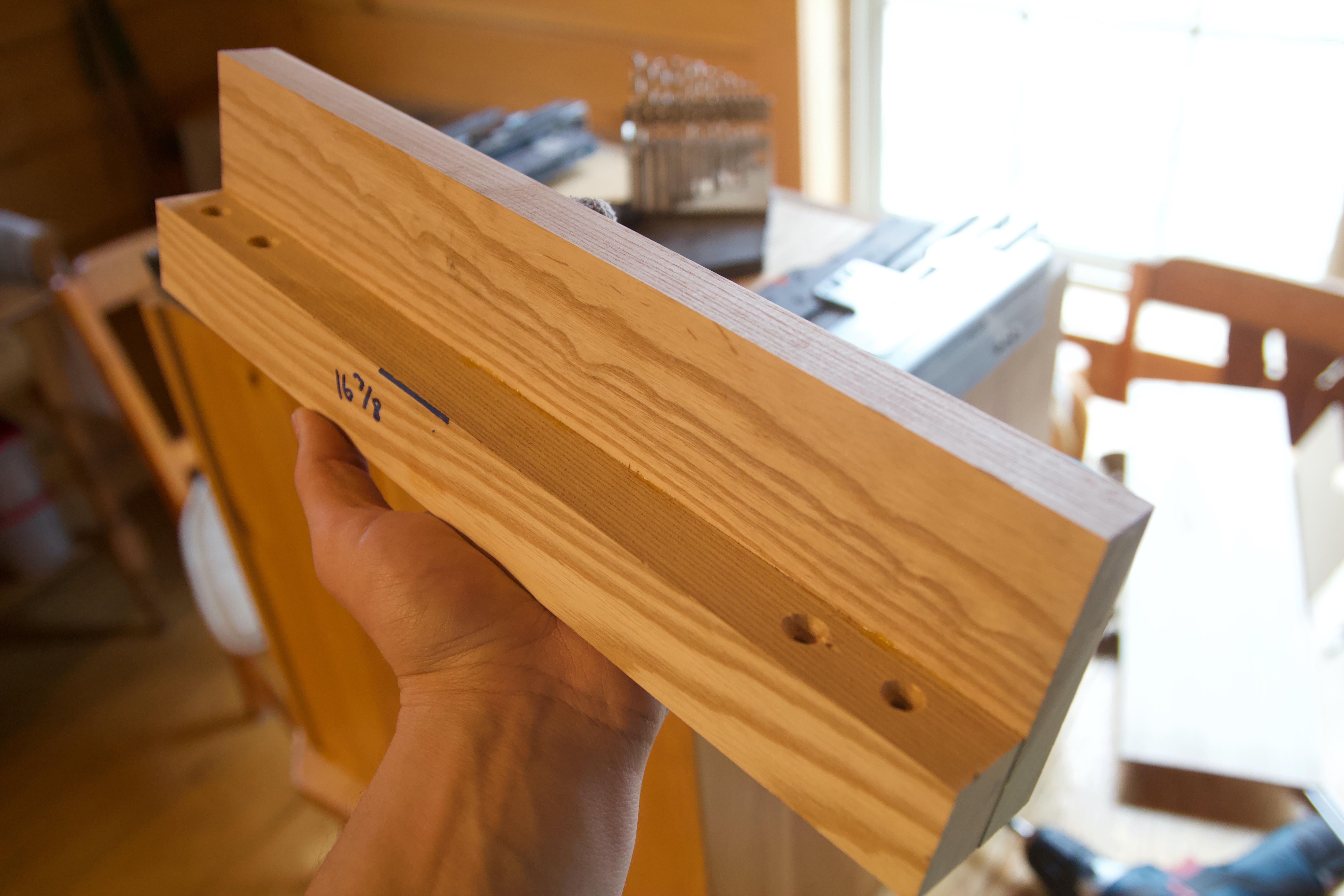
After a bit of head scratching and research I resolved that I should have investigated their mysterious workings prior to going to a location with spotty cellular reception. I did make these cool mounting brackets ahead of time at least.
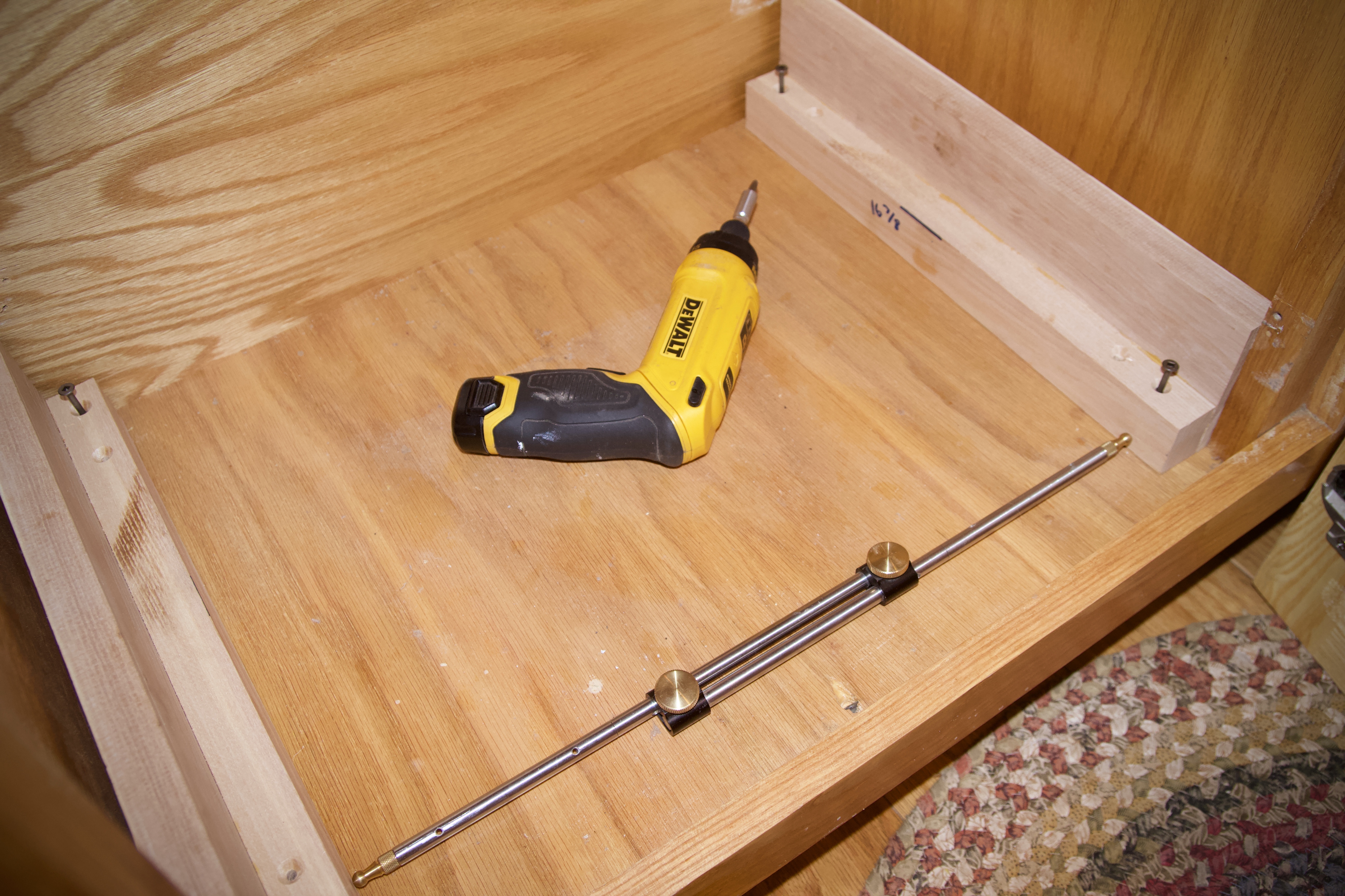
The wood mounting bracket allowed me to start with a perfectly level and parallel mounting surface. Then I installed the fancy Blum Tip-On Movento soft close ball-bearing drawer slides with push-to-open internal catch.
Previously, the trash bin was on a tray that slid out (sort of) being a door that first had to be opened all the way. Problem was the old drawer slides were not ball bearing and the soli ash bin was heavy. The slides were not installed perfectly parallel or level, and bound, only sliding half way out. The action of opening a door first, then pulling out a stubborn drawer that would bump into the door if not fully opened, was a great irritant to everyone.
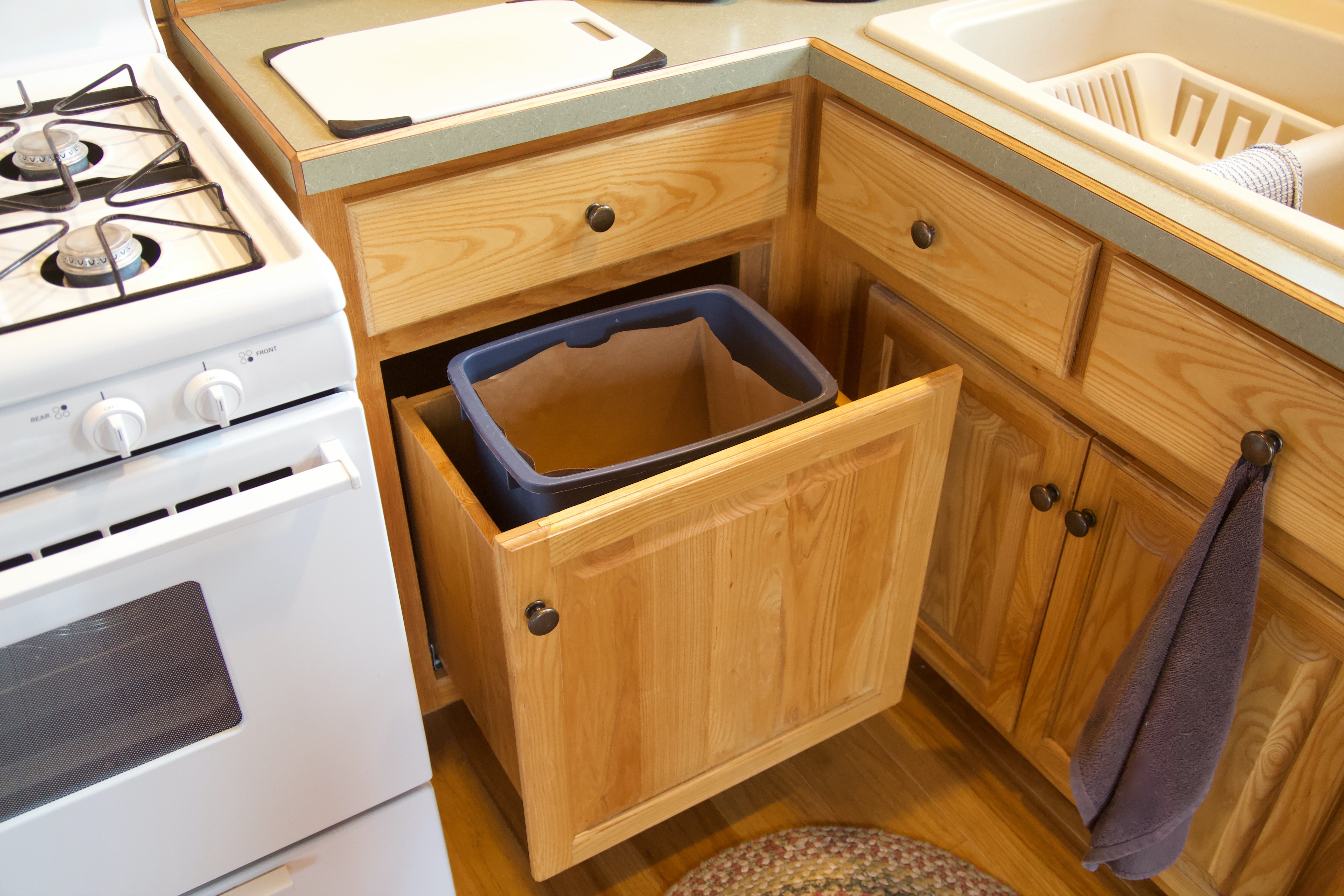
The new slides glide out effortlessly. The door was mounted to the face of the bin and the two move as one unit now. Two options for accessing the trash now exist:
Gently push the front of the frame and panel drawer front and a catch releases and the drawer pops out, gliding to full extension. Closing the drawer resets the catch and then the soft close takes over and drawer glides shut the final inch and a half.
Pull on the knob and the drawer glides out. When closing, the soft close engages and the drawer glides shut the final inch and half. This is arguably smoother since the catch doesn’t have to reset for the push-to-open feature.
The Ol’ man and I were both impressed with our high tech Austrian made drawer slides. They are rated to 40 kilograms capacity for the pair.
A final improvement that has continued to elude me is cellular reception. Initially there was excellent reception with our SureCall cellular booster for both AT&T and Verizon. Then AT&T faded. I’ve been through multiple variations of antenna configurations, each time chasing small gains until no further improvements could be made. Then the signal faded all-together. I settled and decided to set up for the best possible Verizon reception and gave up temporarily on AT&T. I discovered a way to set up a $45/month unlimited plan using an iPhone 6S on a virtual network (Spectrum) that uses Verizon towers for service. I use a small Travel Router tethered to the iPhone to create a wifi network at the cabin so our phones continue to work despite no AT&T reception. We can even make phone calls on our phones over the wifi network. This is an ongoing problem that I’m still actively working on. At this point I’m starting to suspect that AT&T changed something on the tower that used to provide service to our cabin.
Over the past year a few changes have taken place. The biggest update was the inverter. Back on August 24, 2018 the Ol’ man noticed something that he thought was odd. He couldn’t hear a cooling fan running on the inverter. We examined the inverter. After a bit I pulled up some information and figured out the exact nature of the problem… it was the Ol’ man. The inverter was operating 100% perfectly. The Ol’ man thought that a fan stopped working that should be running continuously.
He saw two fans and neither was running. I discovered that there are three fans total. The continuous fan is on the back of the inverter (against the wall) and cools the circuits. It runs continuously and moves a very small amount of air nearly silently. The other two fans activate at the same time when the unit reaches a certain operating temperature and keep the unit from heating up to greater than 120°F – at which point it would automatically turn off. Phew… we thought for a moment the inverter was starting to fail.
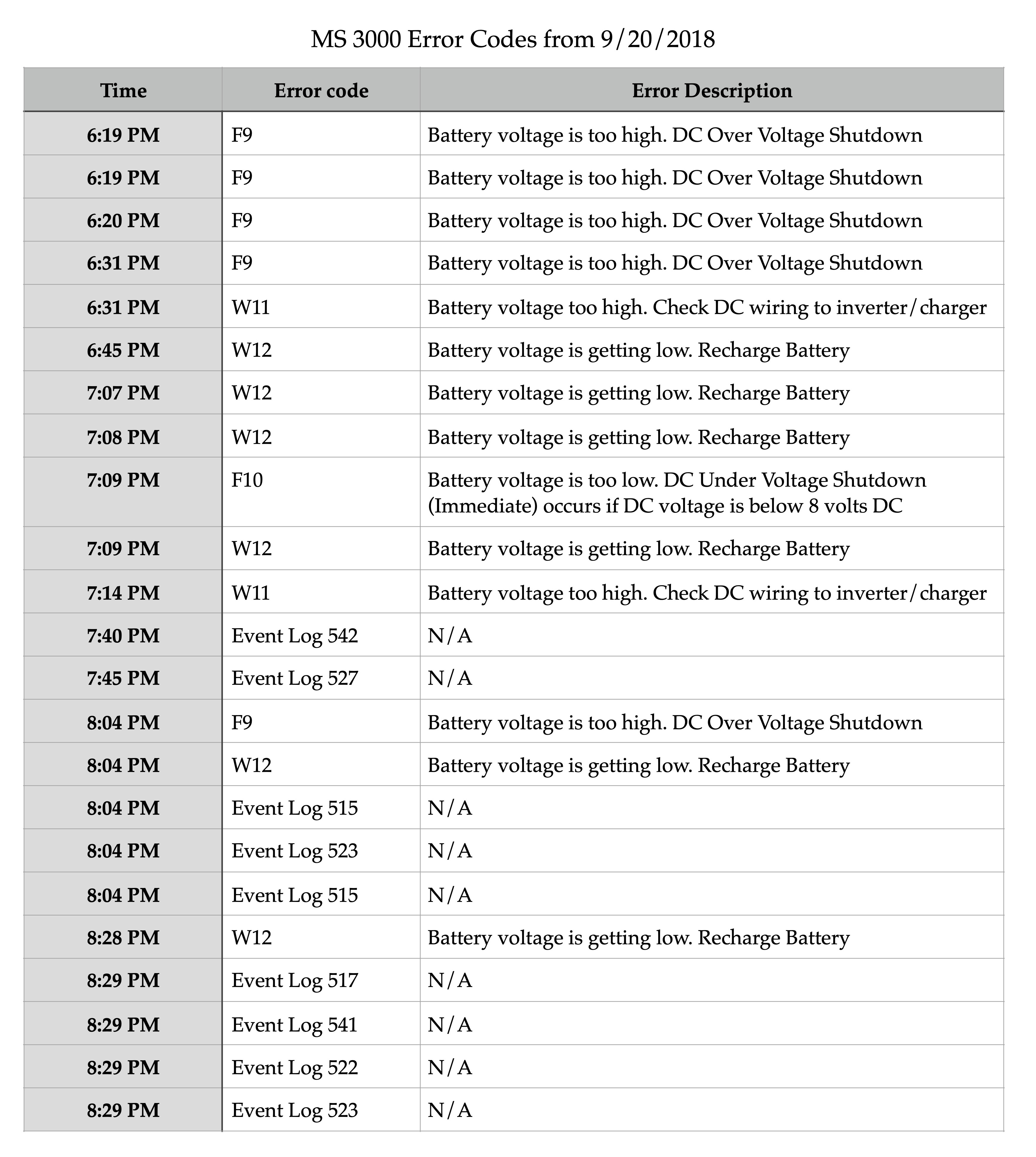
Then on September 20, 2018 at 8:55pm I got a text, “Inverter meltdown, lost power, Xantrex meter not working.” A bunch of warning and fault messages started to show up. We text back and forth a bit trying to reset faults and cycle the inverter on and off in the hopes the issue resolves without further issue. No luck. The Ol’ man ran the generator on bypass mode for the reminder of his visit at the cabin.
I started researching and the Ol’ man started recording data before making a few phone calls. The inverter is no longer supported and we cannot get parts. Here is the data recorded that night:
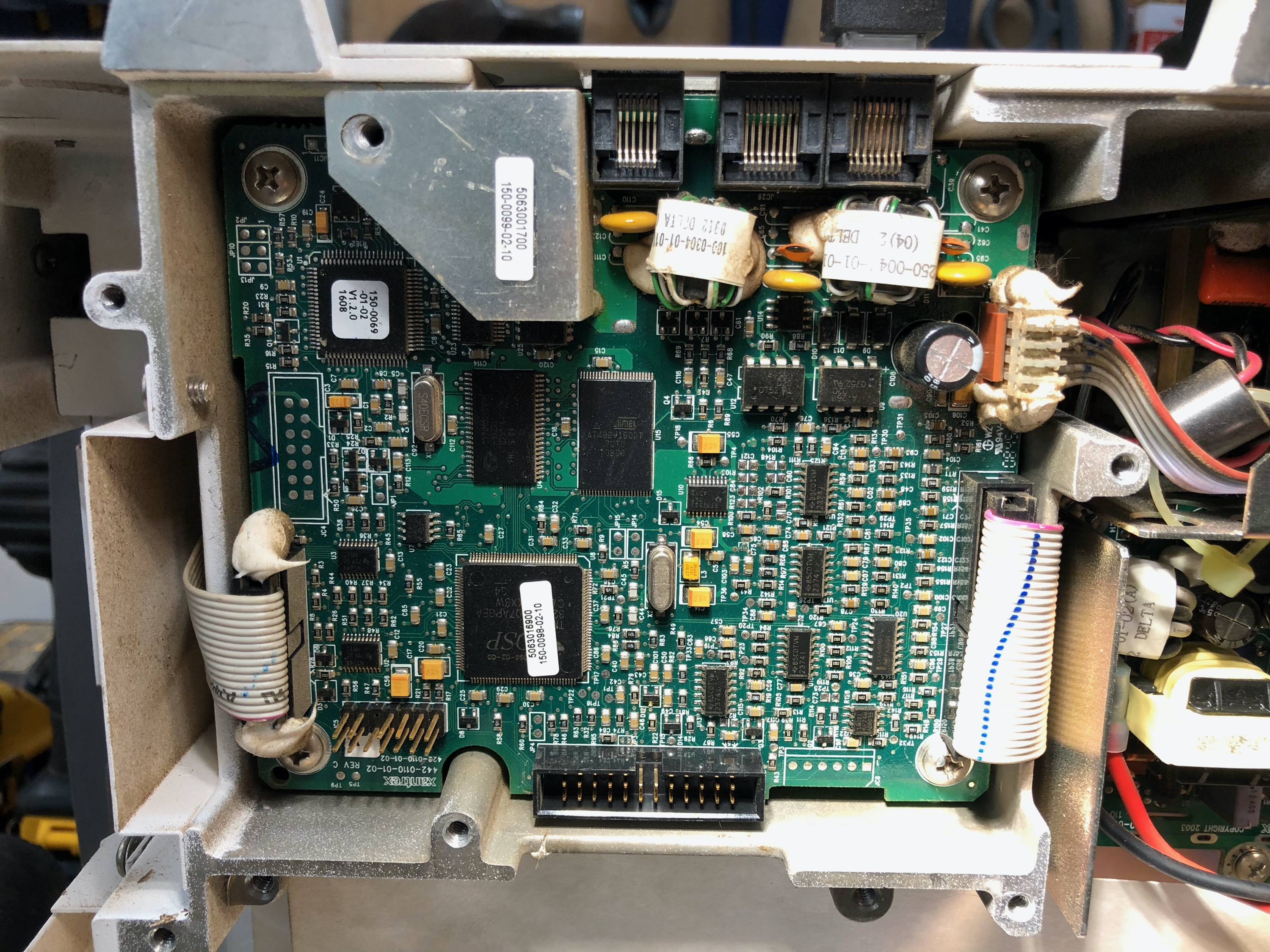
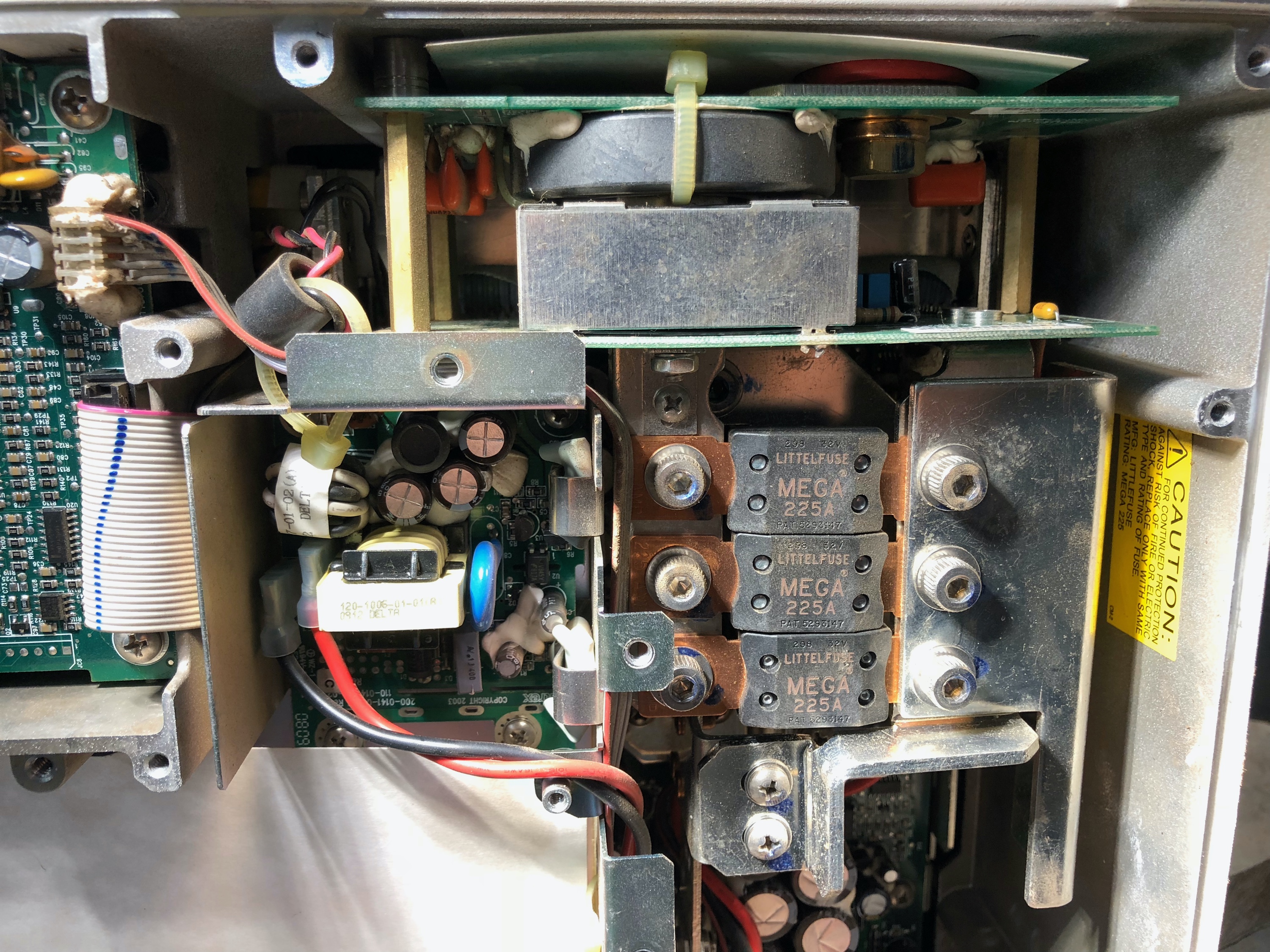
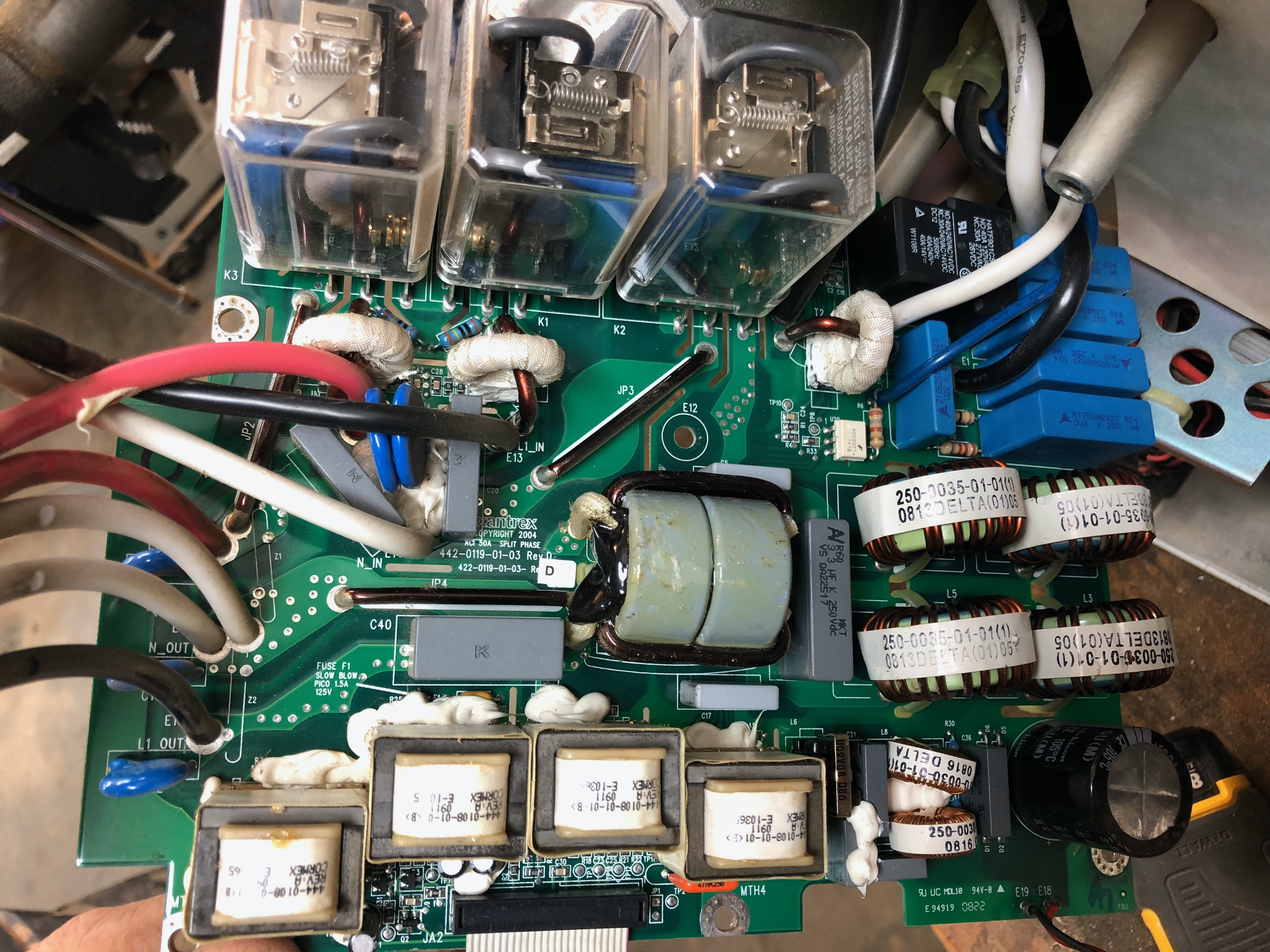
At this point we were stuck. No parts are available, no one locally could repair it, the manufacturer doesn’t support it, and I’m not even sure if there was a bad part that I could find it. The inverter was visually inspected and my untrained eye could find no obvious signs of failure. Have look.
So we moved to plan B: replace it. The direct replacement to our old Xantrex MS 3000 model is the Xantrex Freedom SW 12V. Here is a quick comparison of the key features and differences.
series stacking is new
full output to 104°F (was 122°F)
6000 watt surge (was 7500 watt)
output frequency is 60 Hz +/- 0.2 Hz (was 0.05% or 0.03 Hz)
battery charger voltage range 5 – 16 Vdc (was 10 – 15.5 Vdc)
no load power draw 3 Amps (was <20 watts, new one no longer lists search mode as feature)
max input battery charge 24 A rms (was 22 A rms)
dead battery charge feature (not on old model)
transfer time <20 ms (not reported on old model)
operating range -4°F to 140°F (was -4° to 122°F)
storage range -40°F to 185°F (was -40° to 122°F)
size7.75 x 13.5 x 15.25” (was 8.17 x 13.25 x 16”)
weight 73.7 lbs (was 70 lbs)
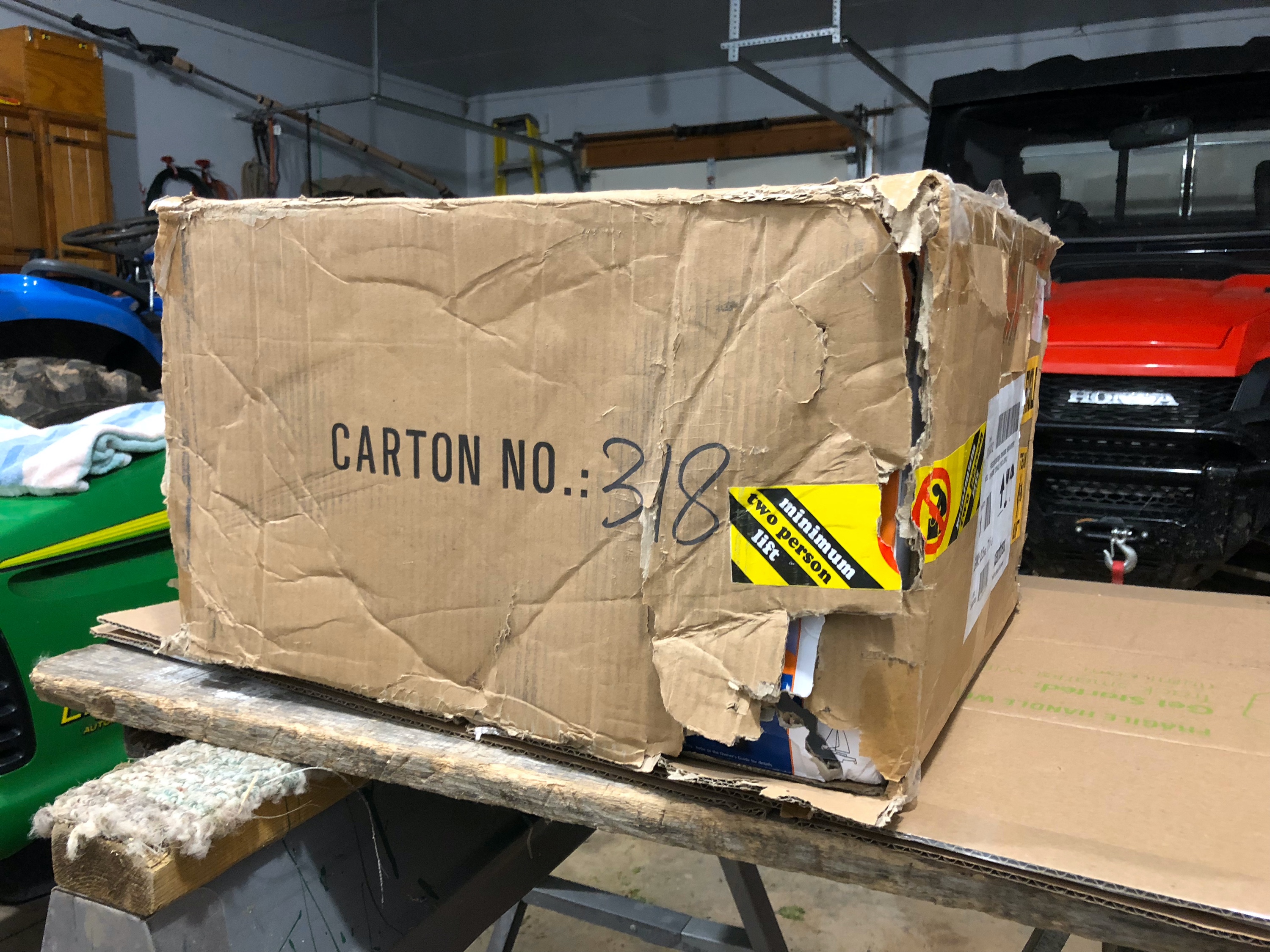
On September 28, 2019 we received the new inverter. The box looked pretty awful. Not surprisingly the inviter inside suffered a fair amount of damage as well. The damaged inverter was installed and put to use until a replacement arrived and we could return the damaged unit.
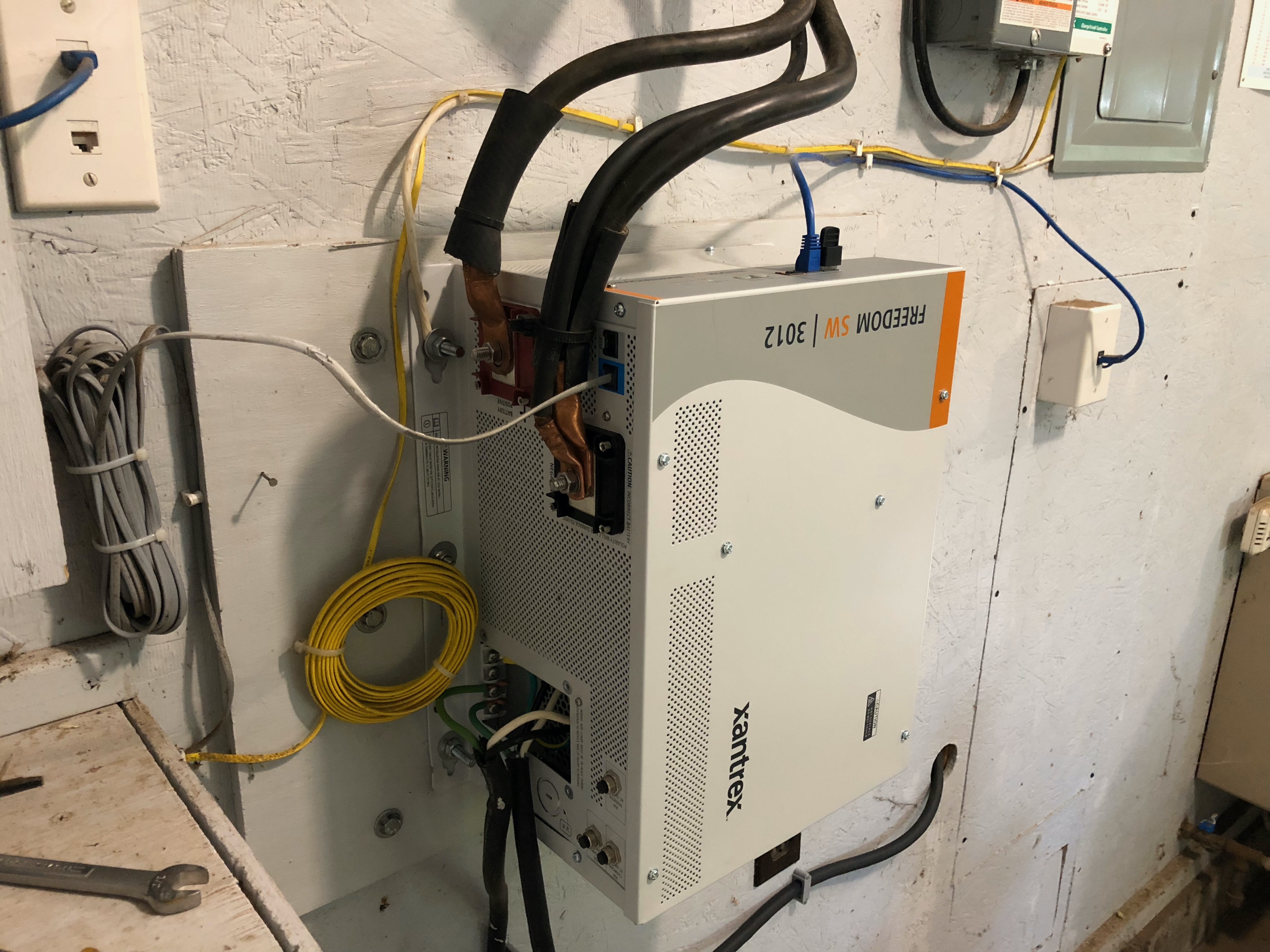
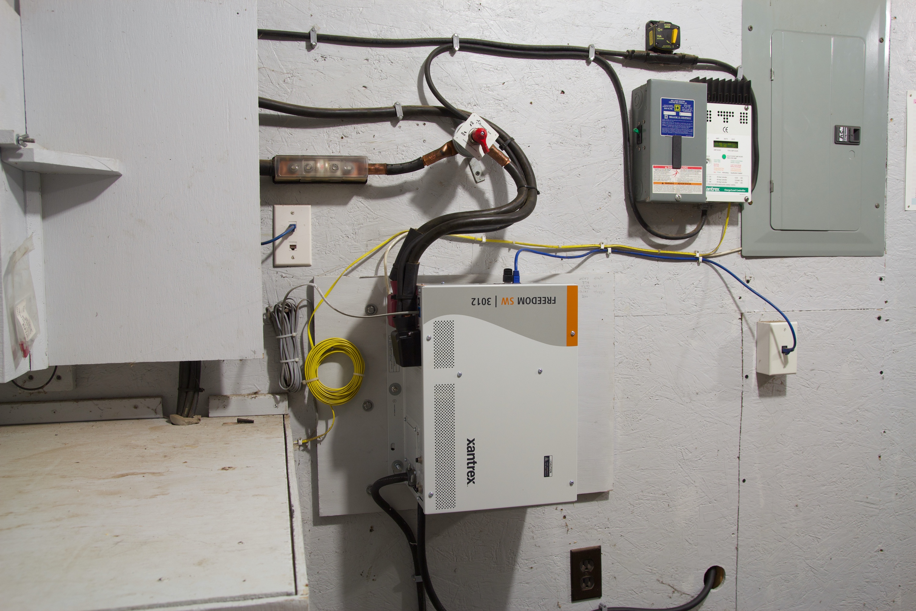
On October 11, 2019 we finally got everything sorted out I did a cleaner installation and tidied up all the wiring. The replacement inverter arrived with significantly less damage from shipping (there was still some, but it was small and we were tired of hauling around inverters at this point). At this time we also installed a new control panel. Not surprisingly, the old control panel in the cabin no longer worked. It looked identical to the new control panel but the electronics inside were updated. Since all the screw holes and communication ports were unchanged it was a quick swap.
Finally! Back up and running.
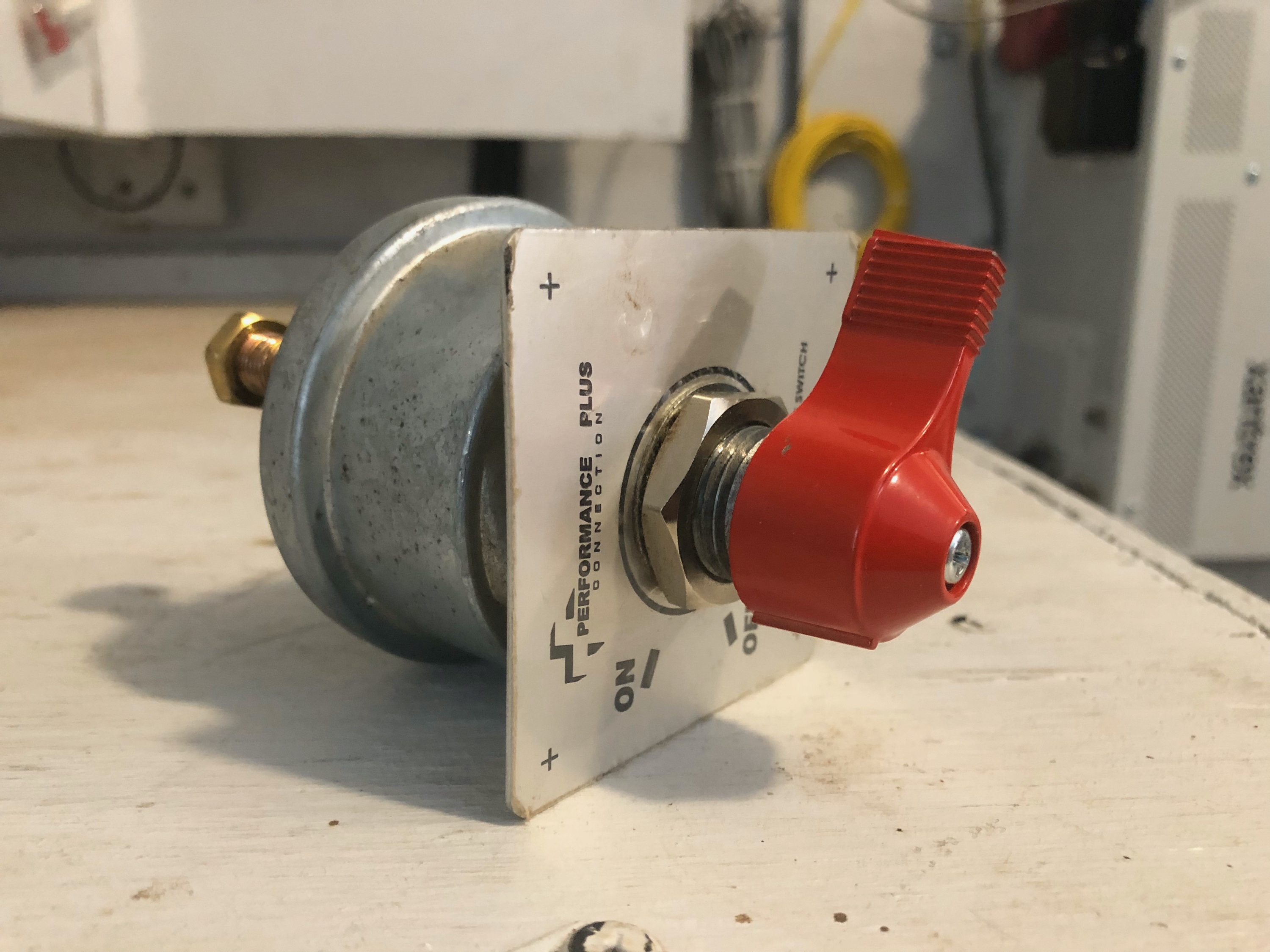
Guess what… random blackouts started a month later. On January 17, 2019 we finally found the issue. The battery disconnect switch was faulty. The switch that failed was supposed to be an upgrade to the original switch we installed back in 2009. The original switch would stick sometimes. In cold weather we would turn it to ‘off’ and it would remain on. It would turn on reliably however. In 2014 the switch was upgraded to a heavier switch that had a more substantial click when engaged. The new switch was sealed and three times the cost of the original.
We went back to the original switch but used some thin lubricant to fix the cold weather sticking issue. OK… finally we were back to normal operation. The new switch, below, has worked perfectly and the new inverter has operated without any issues for the last 10 months.
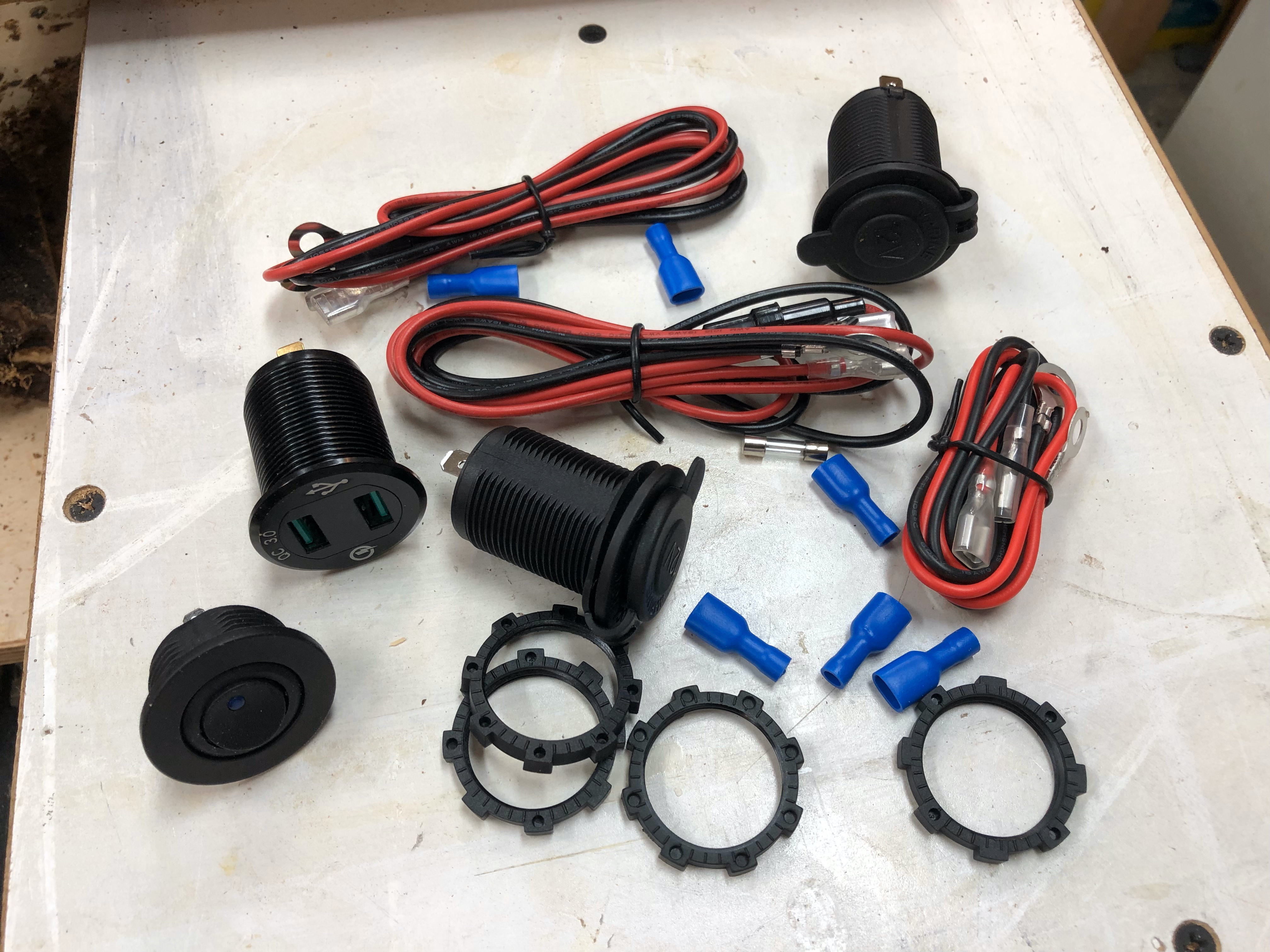
While this was going on I did a quick upgrade to our charging station. Ten years ago when I built the first version in the stairway 12V automative accessory outlets were metal and USB chargers were mostly junk, or phones had proprietary chargers. Jump forward to present day and USB Q.C. 3.0 will do just about everything you want and 12V accessory outlets are going away. I ordered a bunch of parts and started on a redesign.
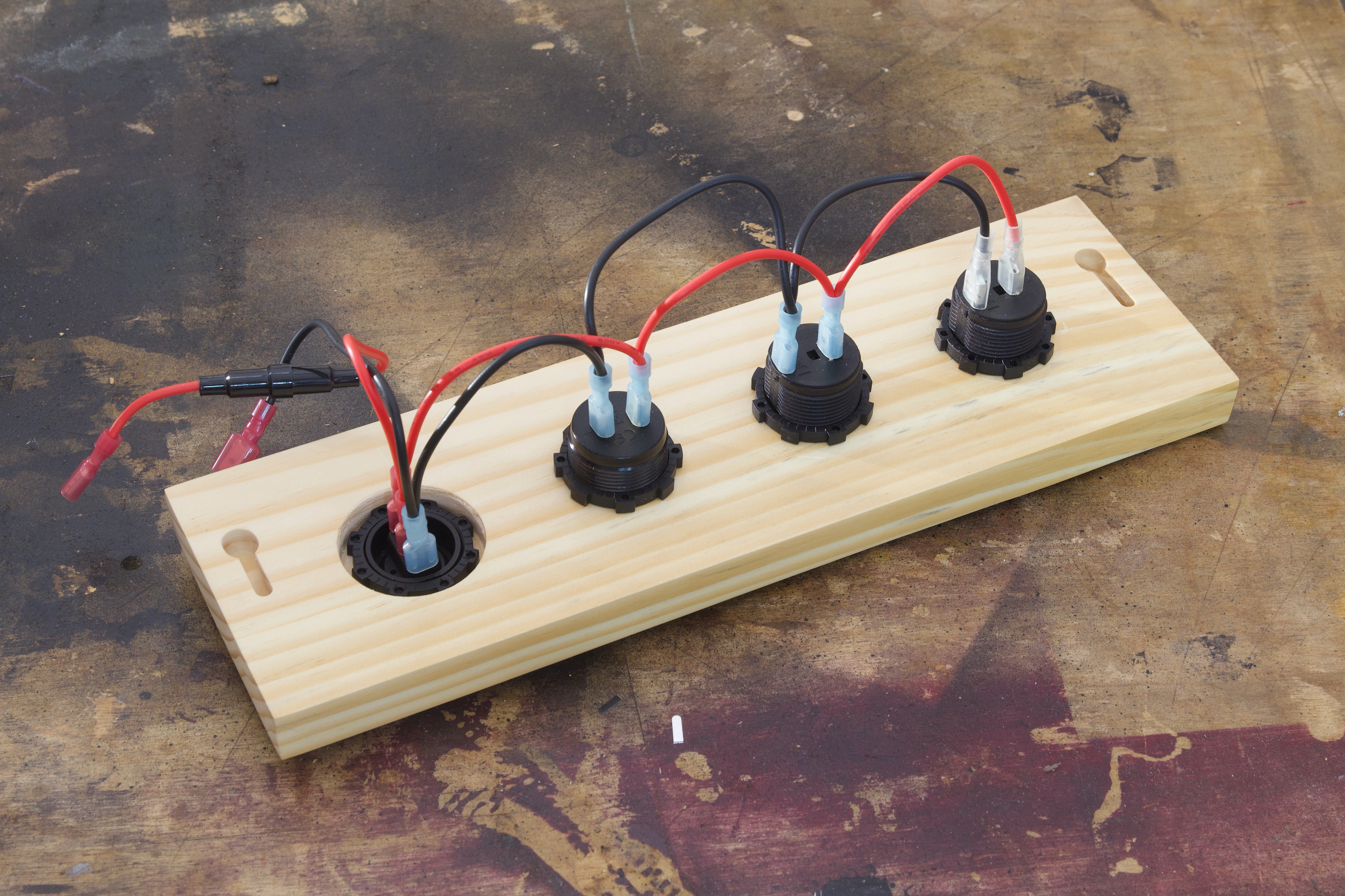
I built a whole new panel and routed keyholes on the back for mounting. The assembly is all set up for quick upgrades in the future. The keyholes allow the panel to be removed from the wall without tools and the spade connectors allow for a new accessory socket to also be installed without tools.
The outlets are on a power switch so we can eliminate unwanted power draws or simply minimize the amount of devices that are under power when we are away. The modular design also allowed me to test everything in my shop before installing at the cabin.
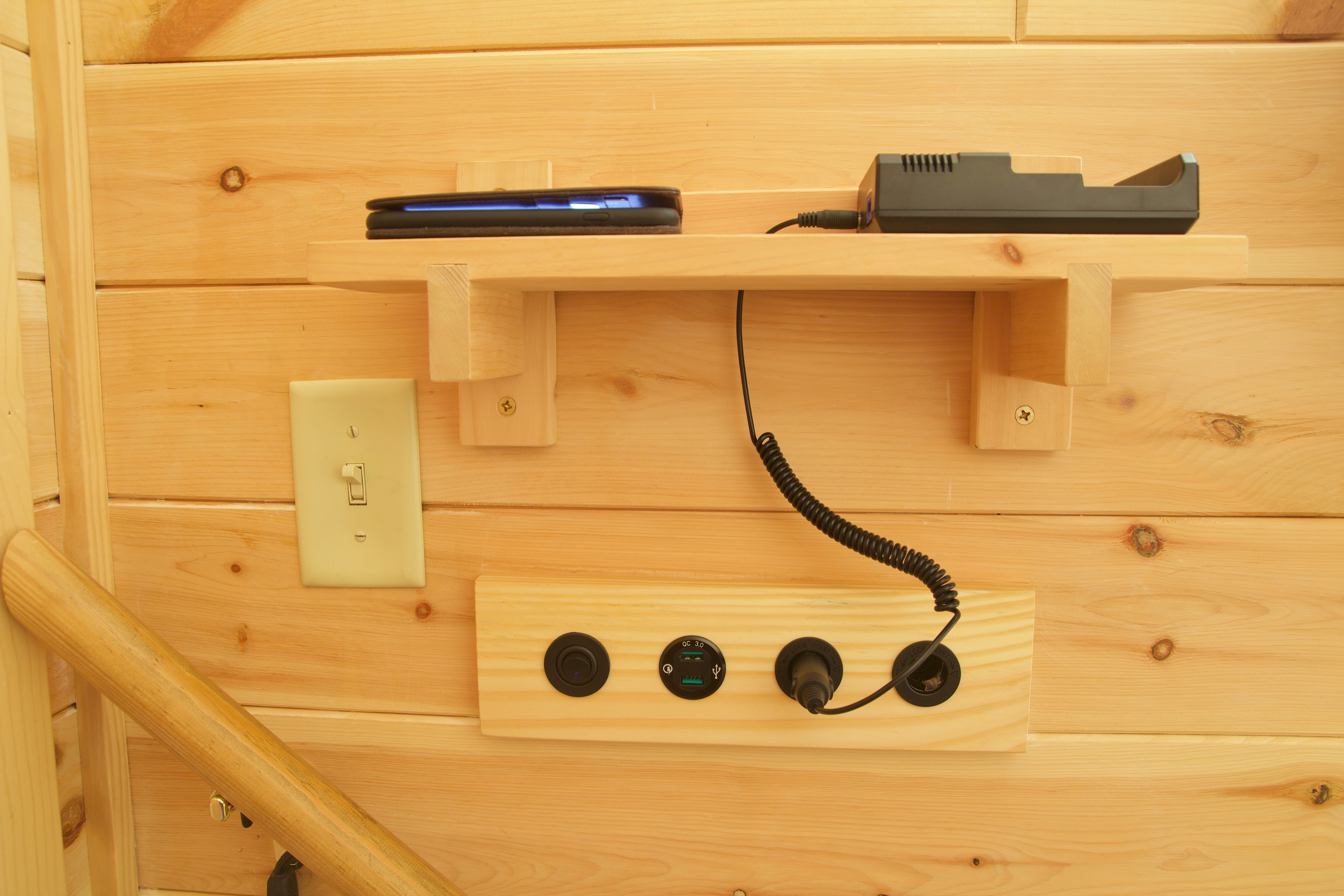
The installation was simple. As devices move from USB 3.0 toward USB C it is now super easy to upgrade the charging station by unplugging and popping out a 12V accessory socket and putting in a USB C charging socket (when the time comes).
And one more thing. The battery bank. I never got around to running a test. The test will be simple and is now planned for summer 2020. I will fully charge and equalize the batteries before running an air conditioner until 100 Ah have been used (as recorded by the Victron battery monitor). Specific gravity will be recorded after equalizing and after using 100 Ah and will allow me to calculate the remaining real-work capacity in the battery bank.
The cabin is a continuing work in progress. This past year there were several upgrades and refinements. The first began late Monday evening on December 4, 2017. The road was still torn up from logging and impassable without a 4×4. The Honda Civic simply wasn’t up to the task. The Ol’ man picked me up in the Honda Pioneer SxS and hauled me and my gear to the cabin. By the time I finally made it to the cabin it was 11:00pm.
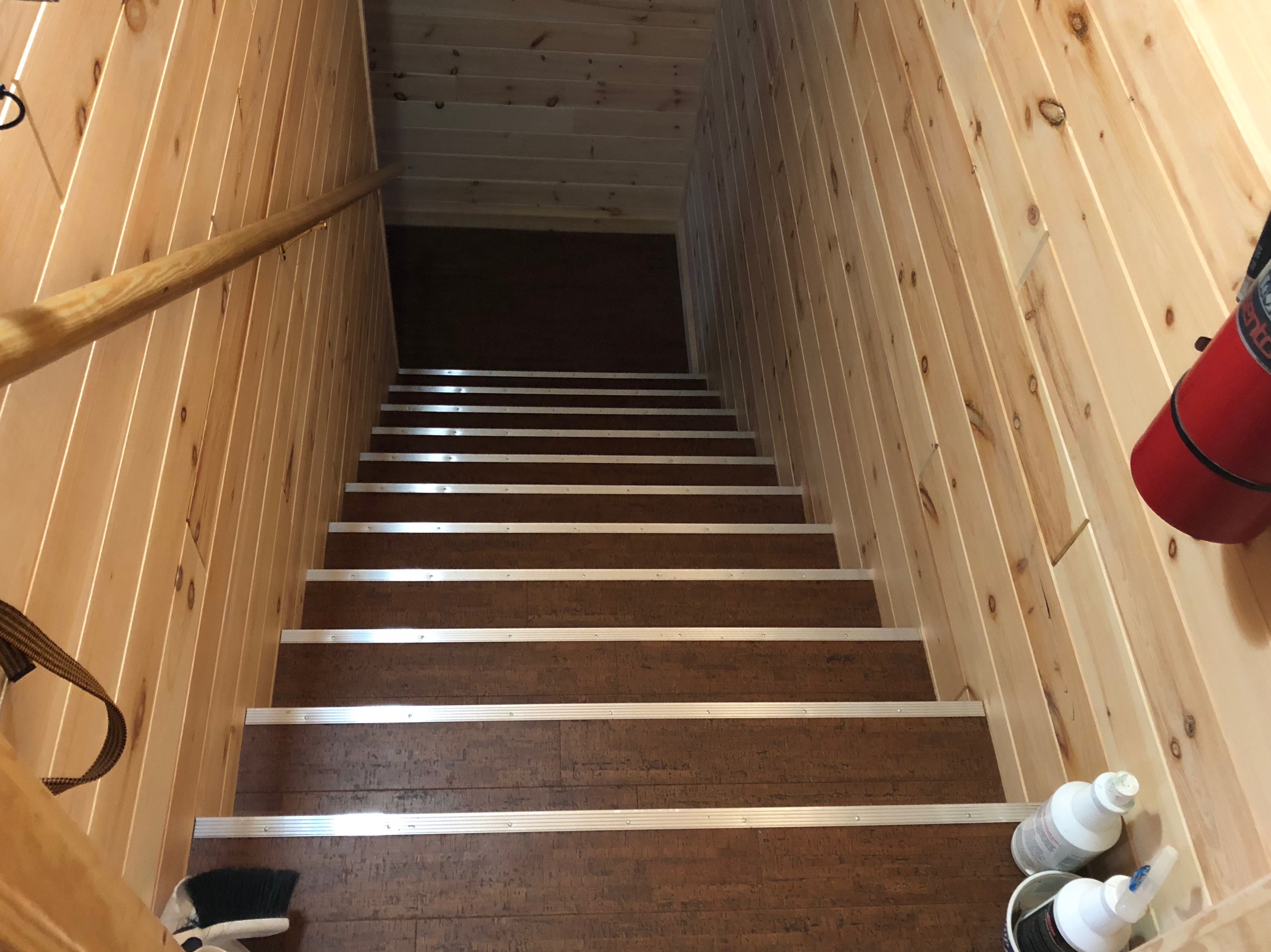
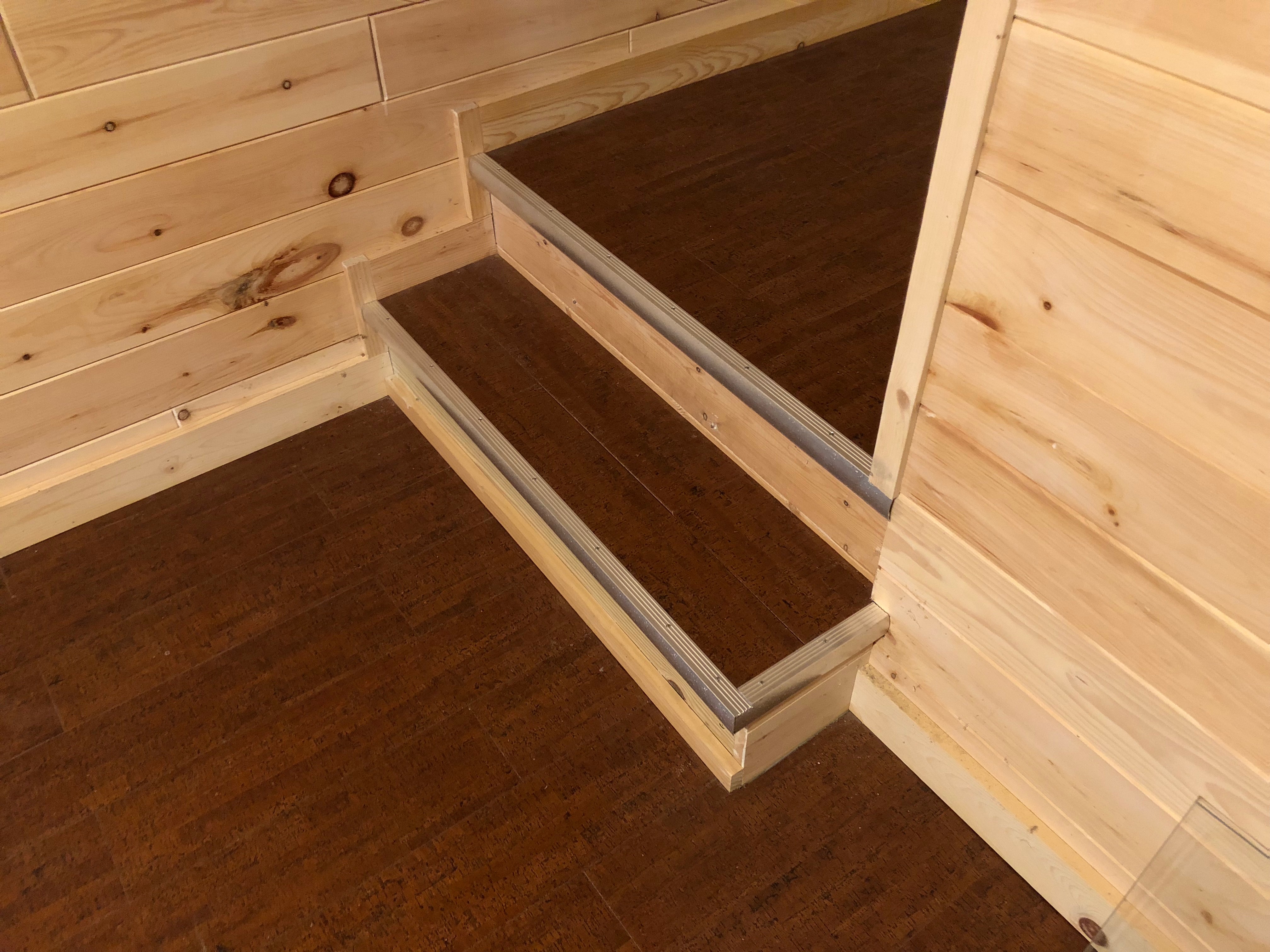
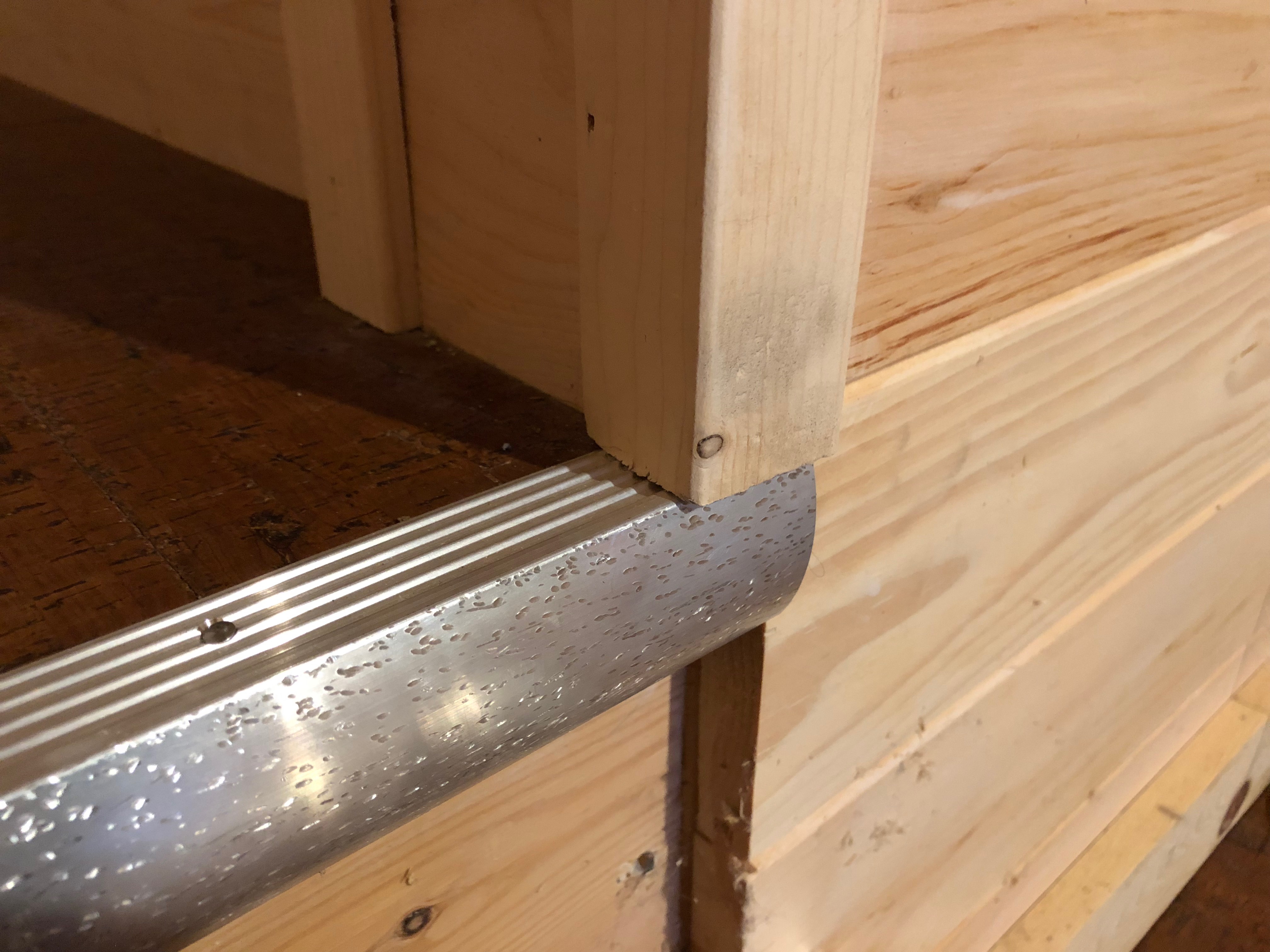
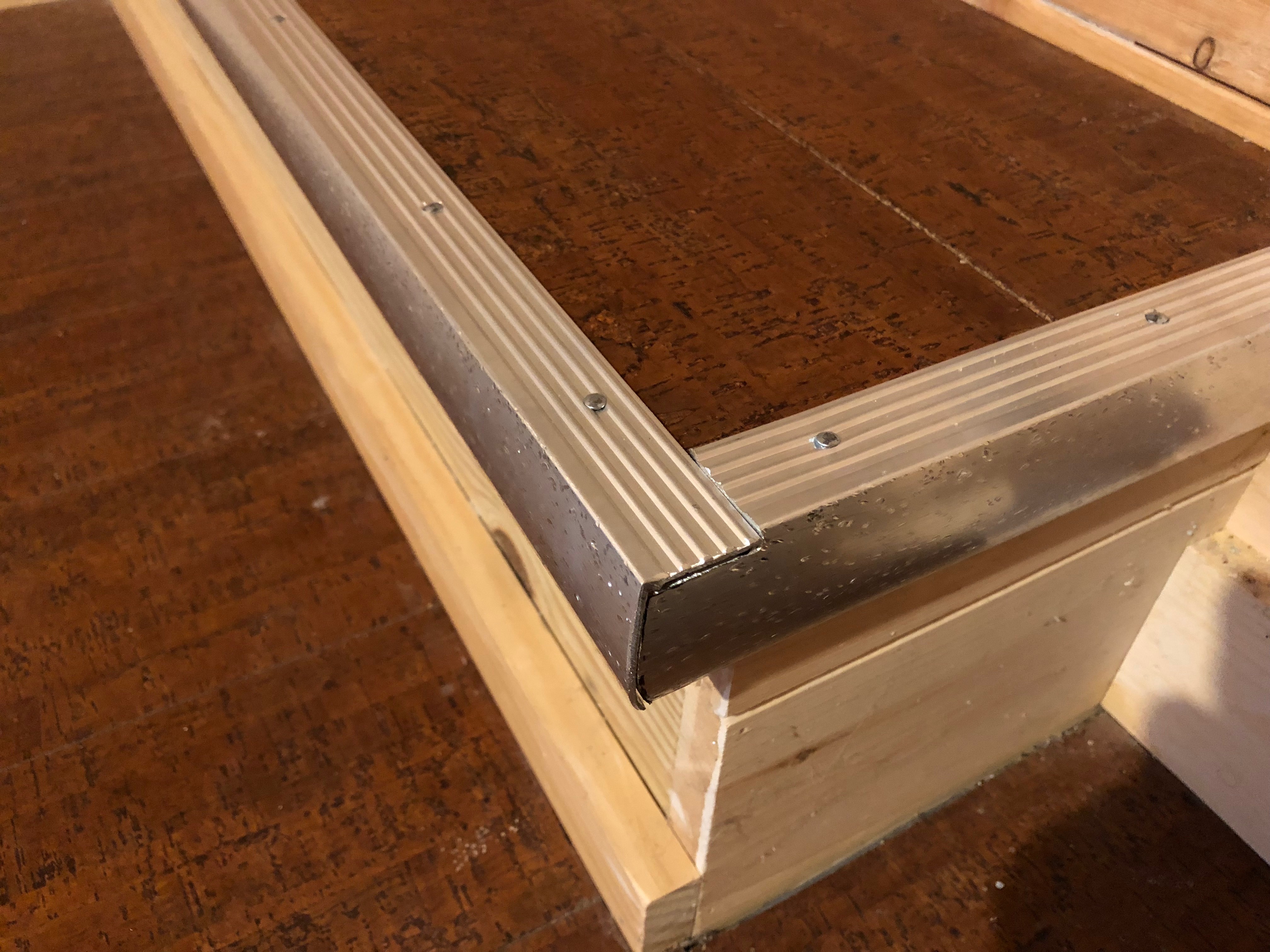
The next morning my alarm sounded and by 7:10am I had a nice view of a food plot. It was a cold and windy day. In my journal I noted that it hit 22°F and wind gusts approached 45mph with sustained wind hanging right around 18mph. The morning hunt was not successful. When 9:30am rolled around I was ready to head in. Back at the cabin a project awaited. I headed to the basement and took inventory of my supplies and tools before starting. Installing the stair edging was a straightforward task. The metal chop saw made short work of the stair edging and an angle grinder with cut-off wheel was used for some of the more complex cuts. The installation went well. Immediately upon completion, the Ol’ man and I tested out the steps and were pleased with the results. The dark stair treads were no longer difficult to navigate. No more sharp edge. The metallic edging made each tread visually well defined and comfortable when traversing barefoot. With wet shoes, there was now suitable grip to prevent a catastrophic misstep.
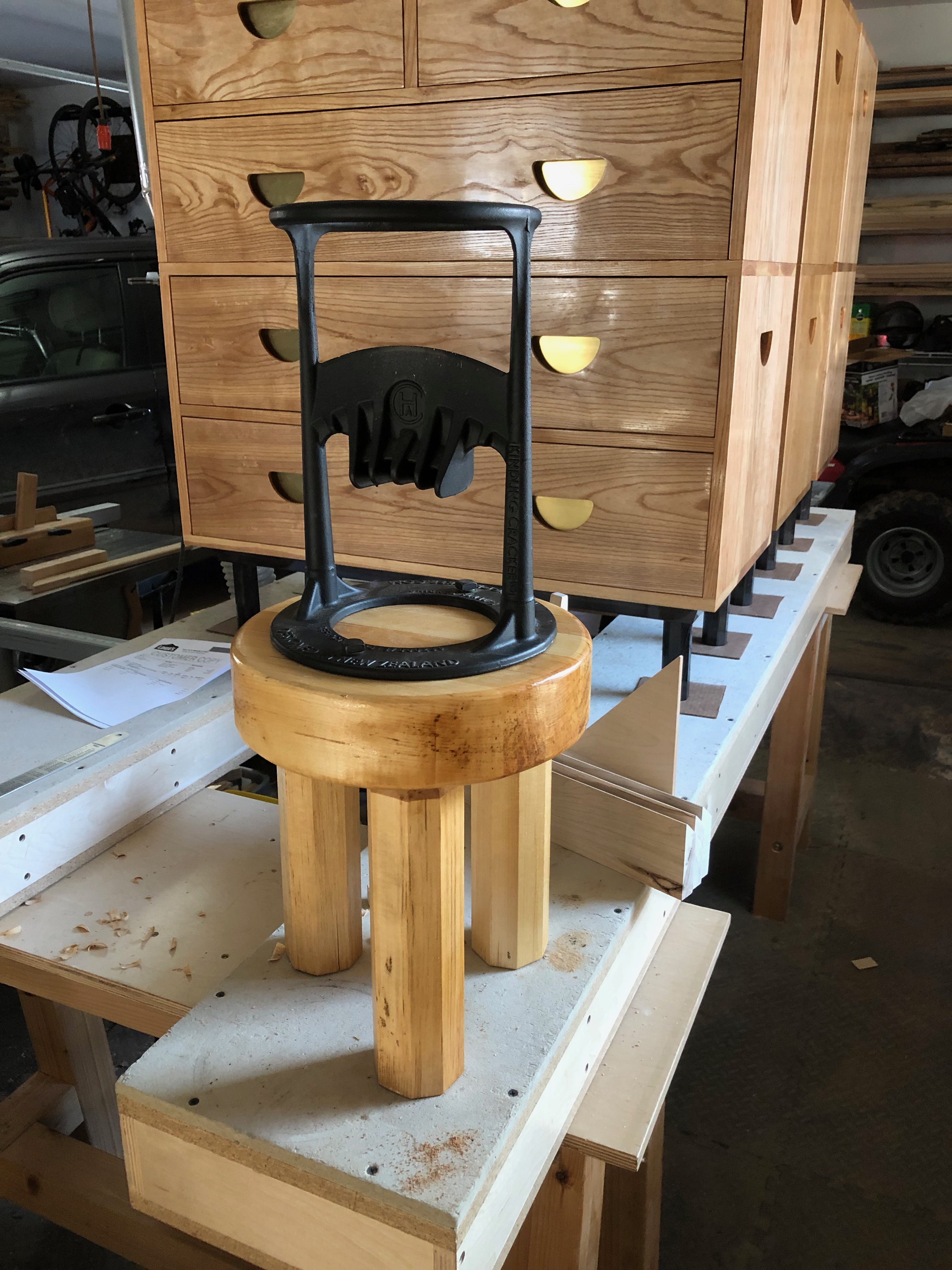
The next upgrade comes via Ask This Old House. It’s probably not too surprising that Ask TOH and This Old House are two shows that I enjoy. While watching one night they showcased a nifty tool for those of us who burn wood and require kindling as a fire starter. A quick search on the internet and I found it! After briefly contemplating which model to buy, I ordered The Original Kindling Cracker from Northern Tool & Equipment. This was late April 2018 and in the wood shop I had just added a lathe to my collection. If you recall, I have no shortage of basswood firewood from the windstorm of 2017. A quick walk to the woodshed was all that was required for some material. In short order I had tested out my lathe and made up a small stool for the Kindling Cracker to mount to.
The Kindling Cracker works lovely. When we run low on kindling it takes only a few minutes to make more. It actually is easy and safe to use. In an armload of firewood there are usually one or two knot free pieces; these are the best kind for splitting into kindling. A tap or two with a 3lb hammer is all it takes. Keep on splitting until the kindling is appropriately sized. The basswood base I built is light-weight and sturdy. The wood is at just the right height for splitting without bending over, and unlike mounting it to a block of wood, the unit is light easy to move around. The Ol’ man is in love with it. My kiddos are also interested and my oldest two cracked a few pieces with the help of an adult.
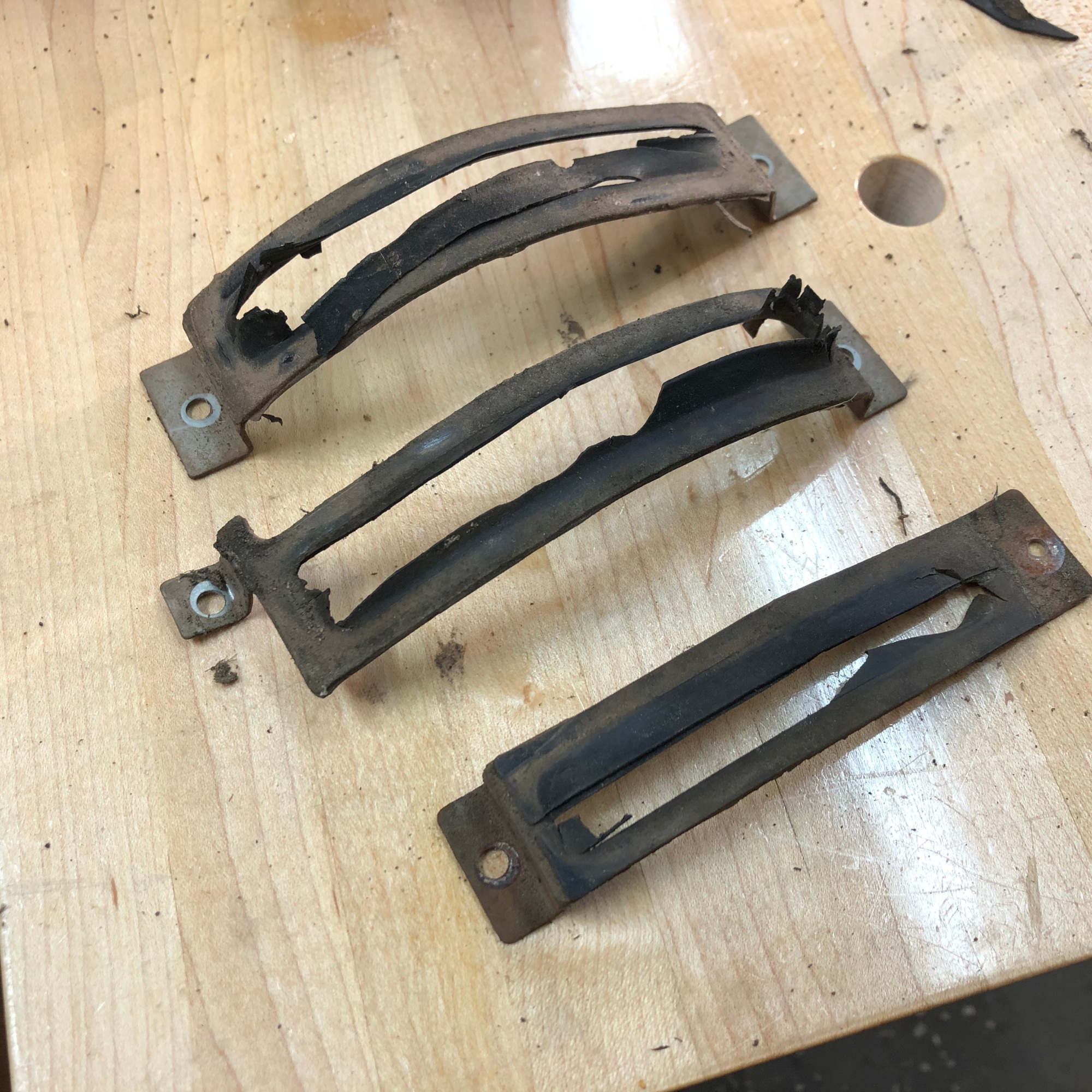
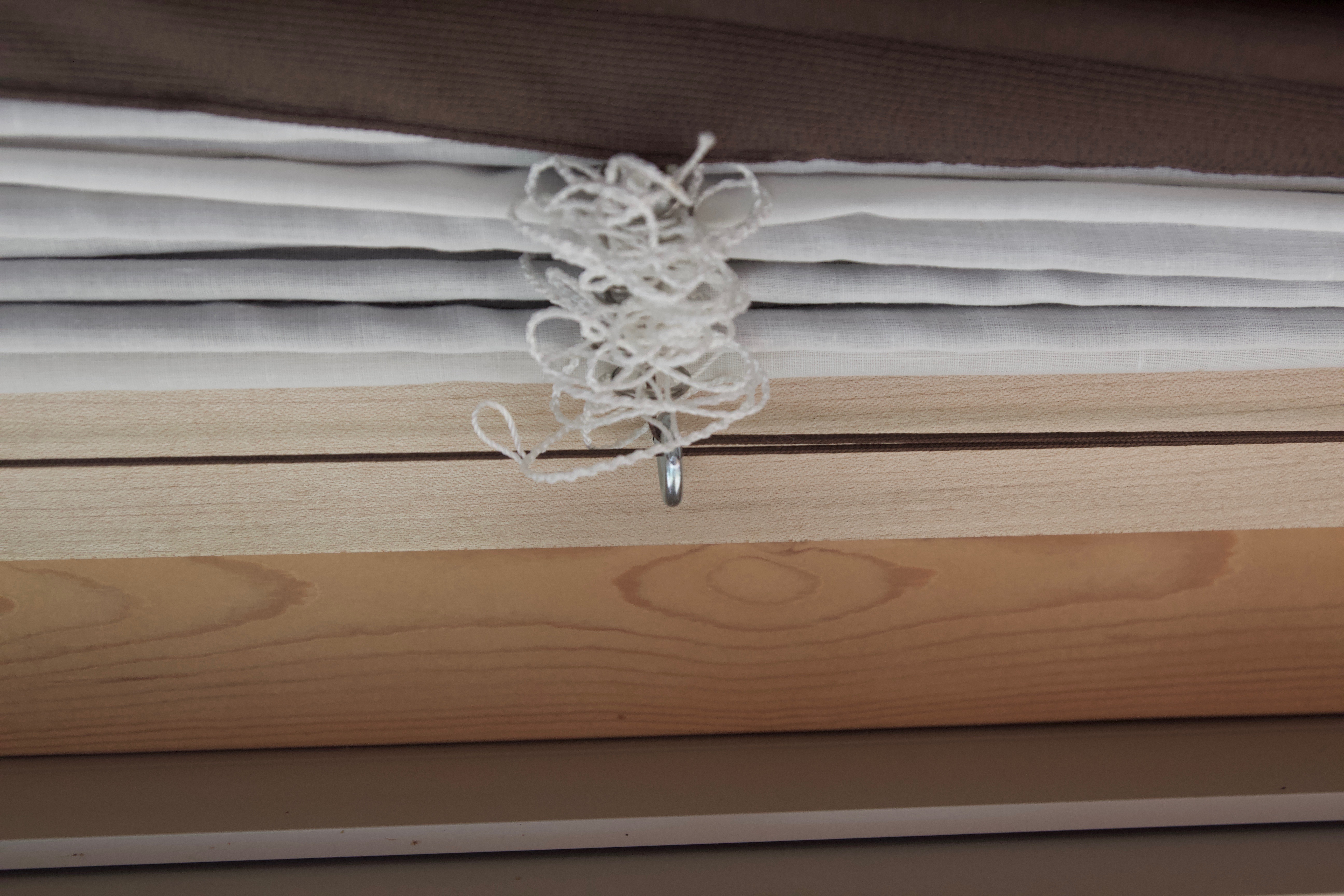
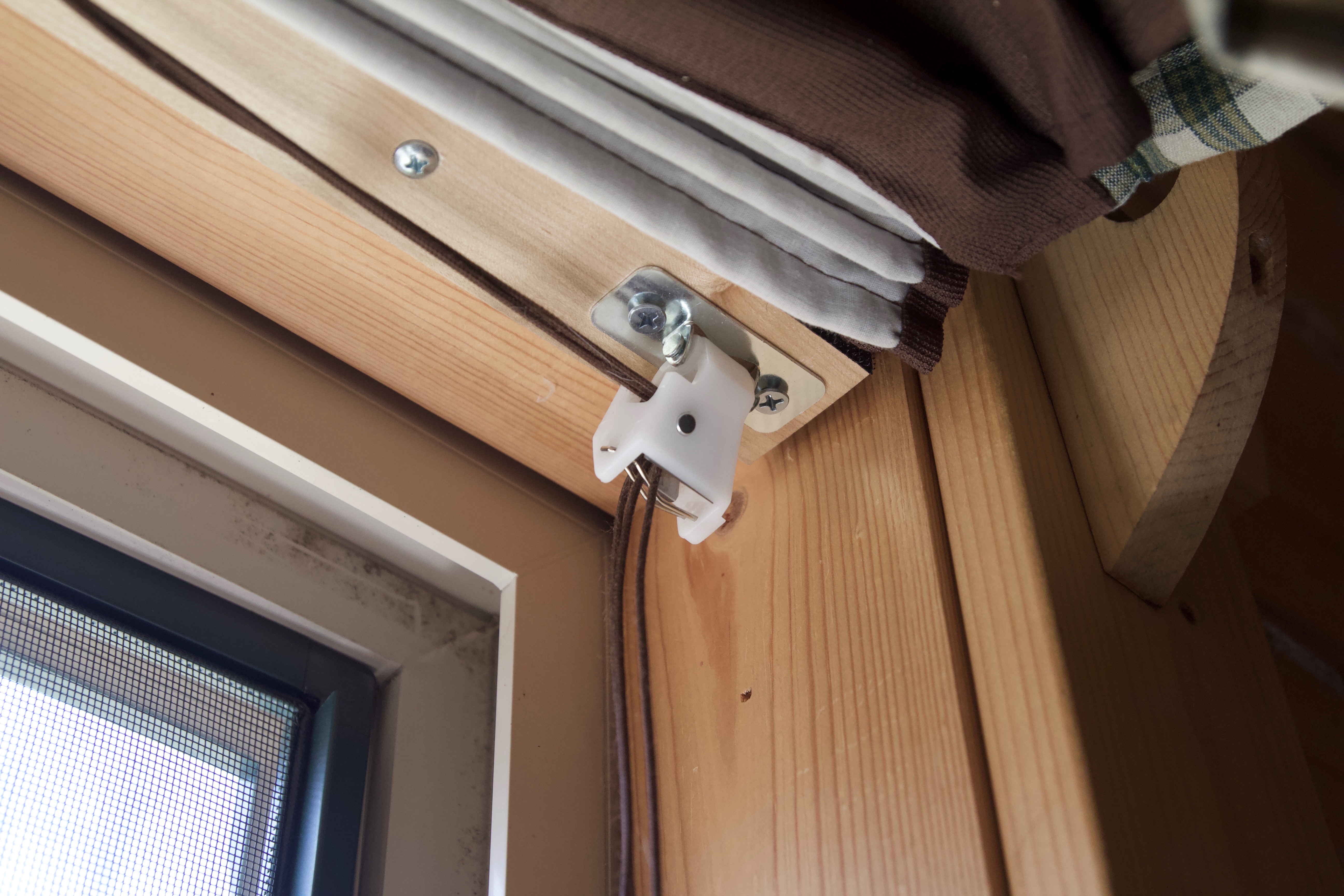
Up next, the cabin’s Roman shades. Mom made sure to install high quality shades in every window suitable. The shades insulate and save energy when we are not at the cabin. Upon arrival we raise the shades, and when we depart they are lowered. While the shades fulfill their purpose to a high degree of satisfaction, the experience of raising and lowering had been fairly unpleasant. The old mechanisms were plastic and the mounting bracket was poorly constructed. With normal use, a few were broken, bent, or functioned so poorly that in order to open and close the shades a short training course was required from a senior shade operator.
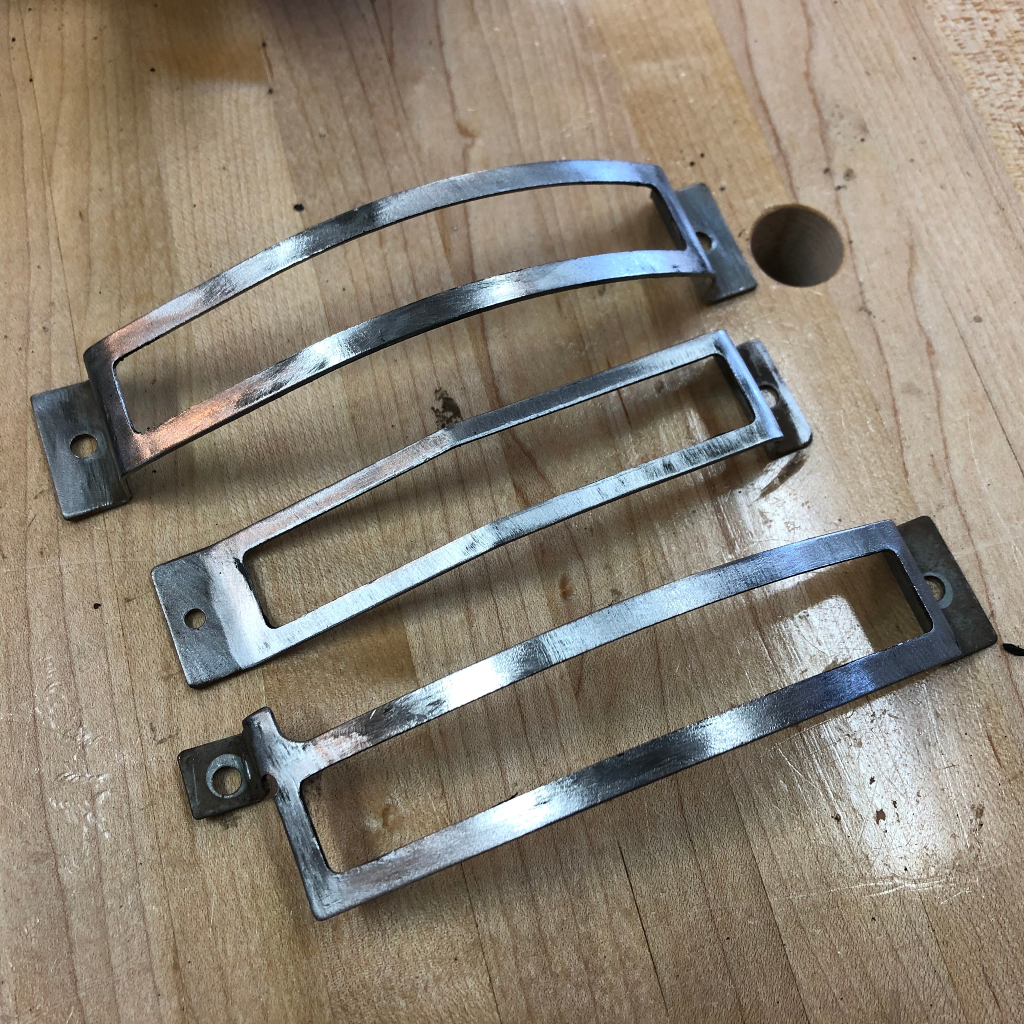
After a little planning and some measuring, I drew up a plan and ordered some parts. The list was fairly short and the materials were less than $20 overall. The plastic mounting bracket was removed and appropriately placed in the trash. The brackets I built were made from soft maple, finished with a clear varnish, and featured upgraded hardware. Small screw eyes guided the string and a much higher quality cord catch was used. After the installation, the shades raised and lowered smoothly with minimal effort and the requirement of a training course in roman shade operations was removed. The Ol’ man approved heartily.
Sometimes it’s the little things that make life better. I get great satisfaction from solving problems and making simple tasks more enjoyable.
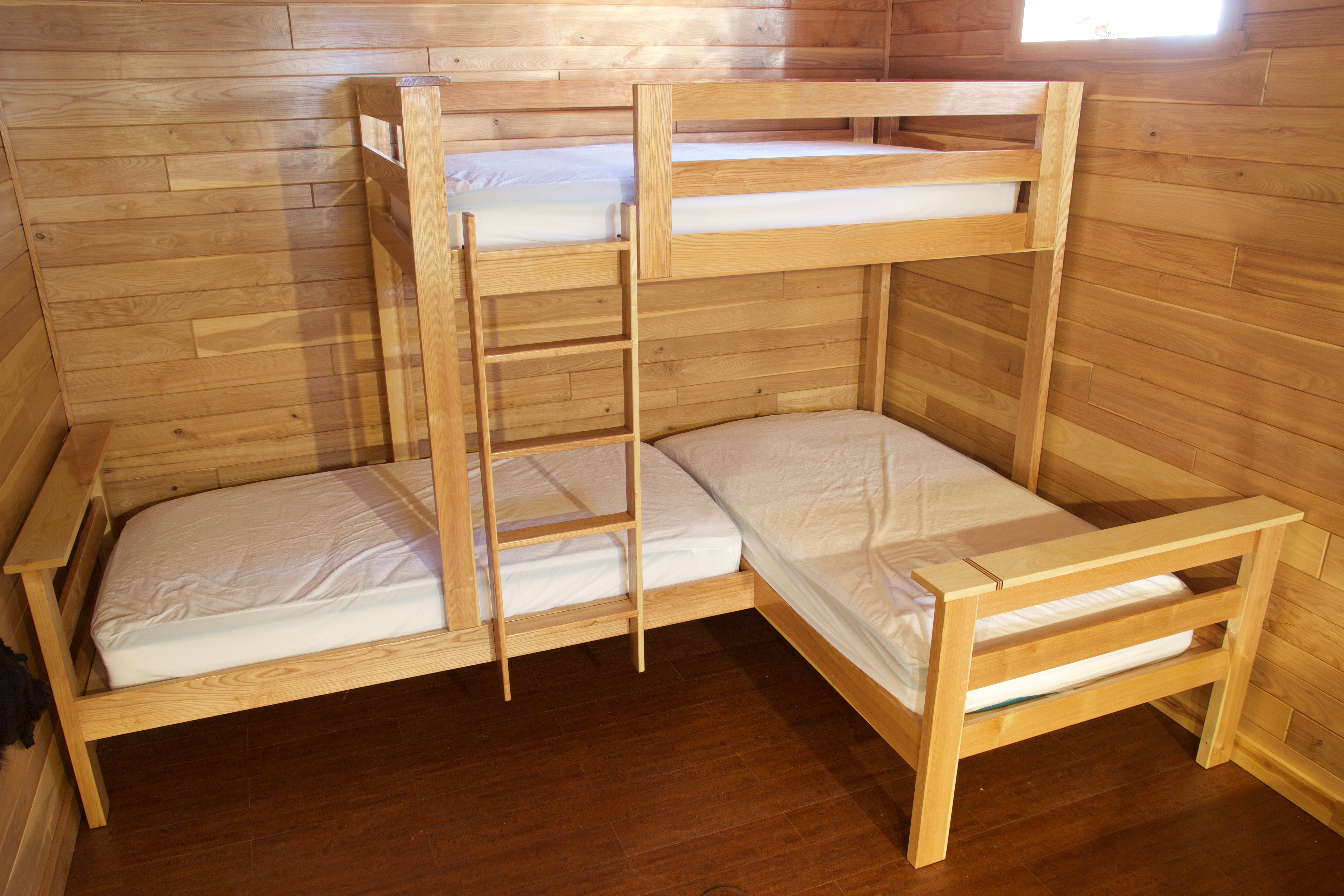
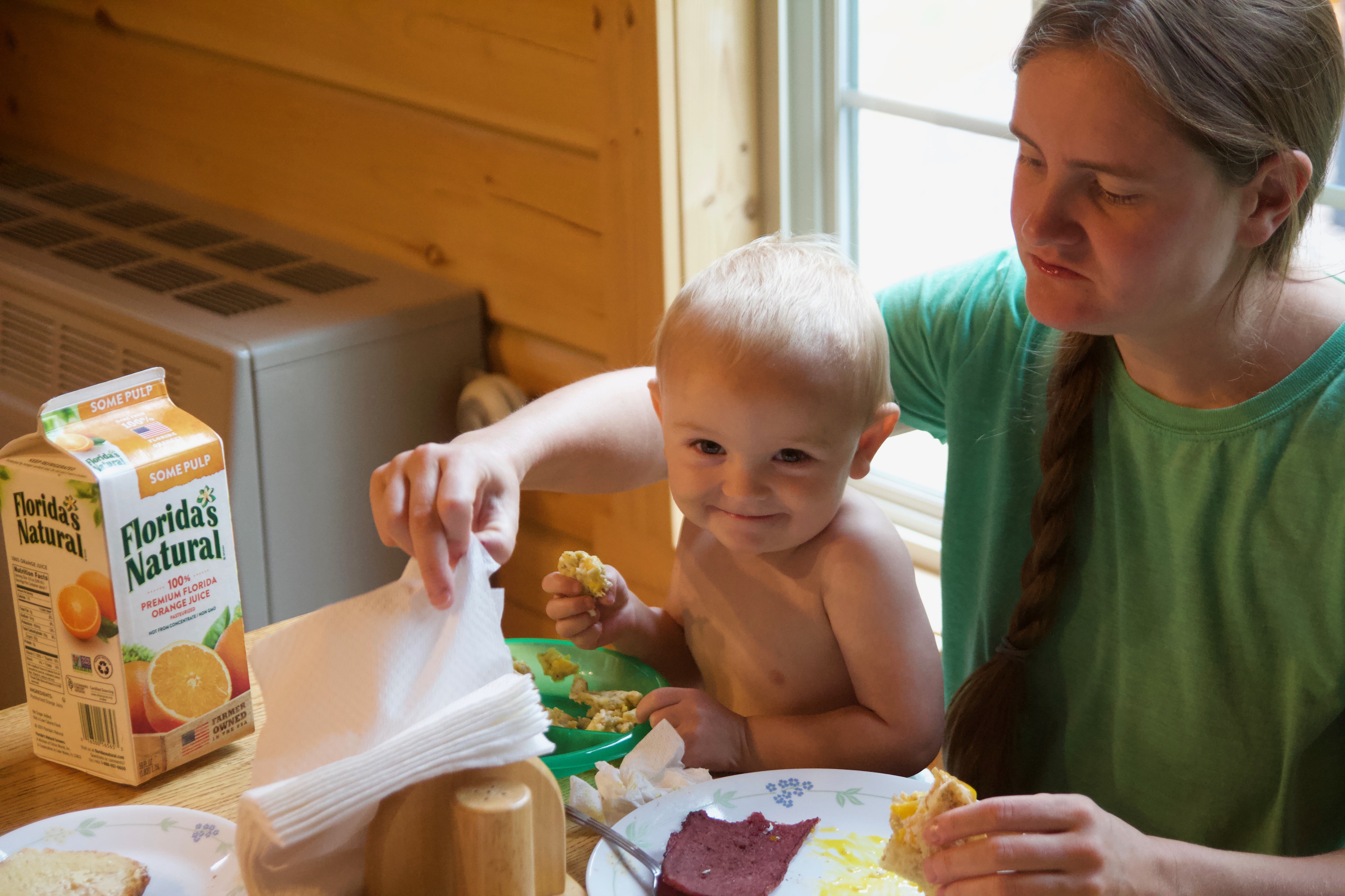
This post is a long time coming. I’ve been working on making the basement into a kiddo storage facility… err… sleeping area. We’ve had a pool table, dart board, foosball table, and TV downstairs in the game room for a while now. What we have been lacking is sleeping accommodations for the three kiddos that my wife and I take everywhere. We have William (6), Charlotte (5) and Felix (almost 2) and having two adults share two twin beds with three kiddos is just not the best way to build fond memories of the cabin. To achieve the goal of happy sleeping children and having a bed all to myself there was a daunting checklist of items to satisfy…
egress door to satisfy safety codes
beds for three
mattresses + linens
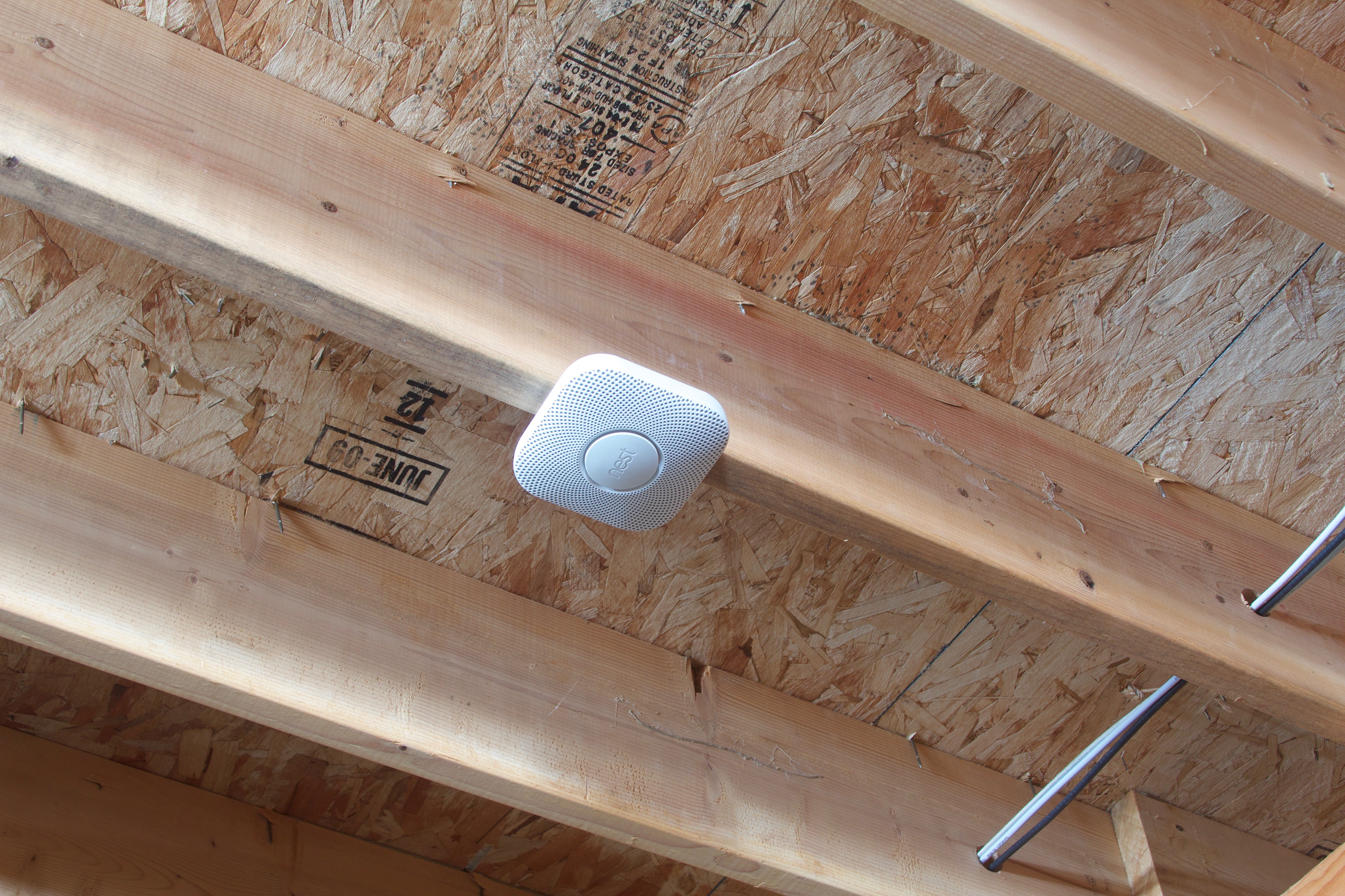
smoke alarms in the basement
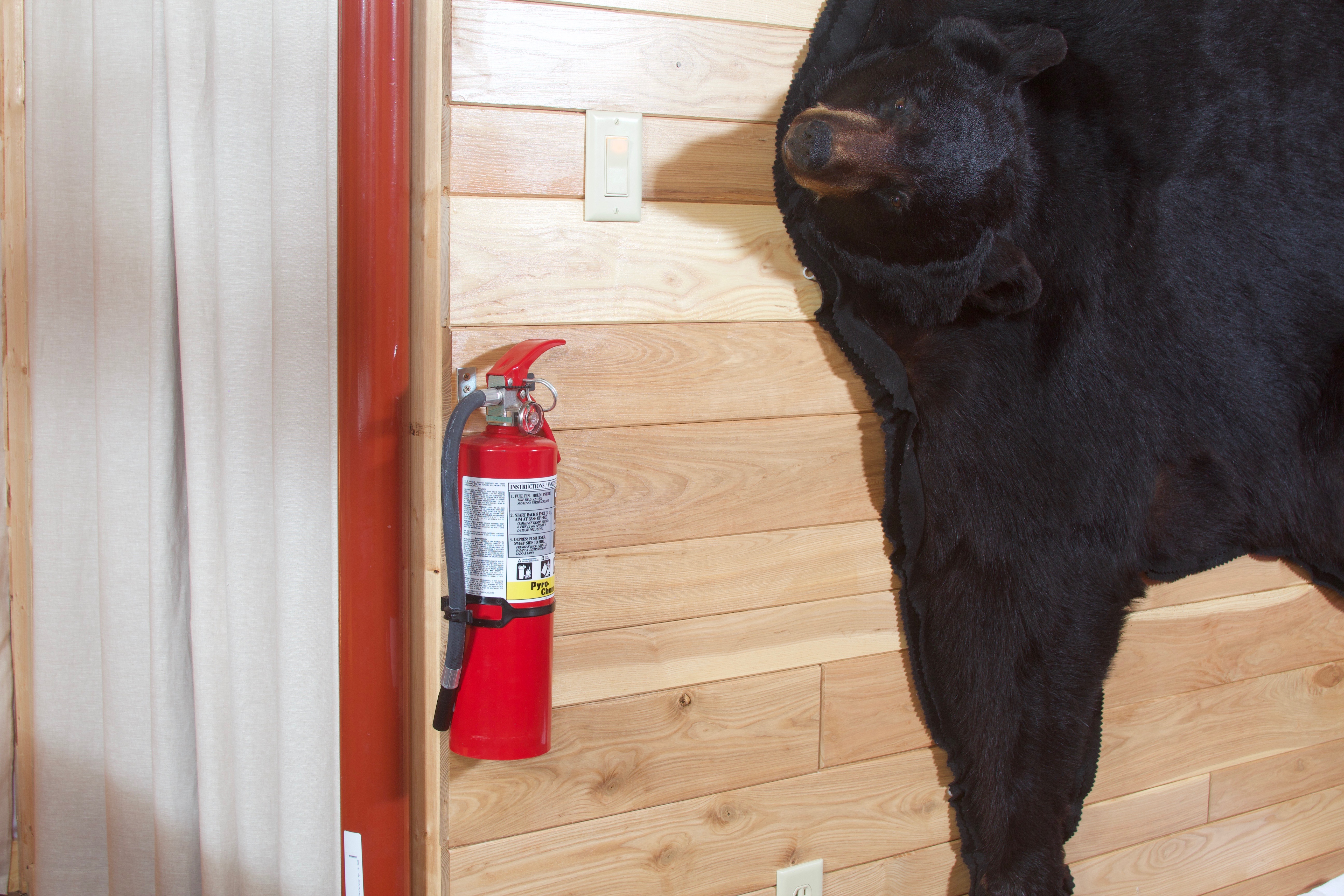
fire extinguishers
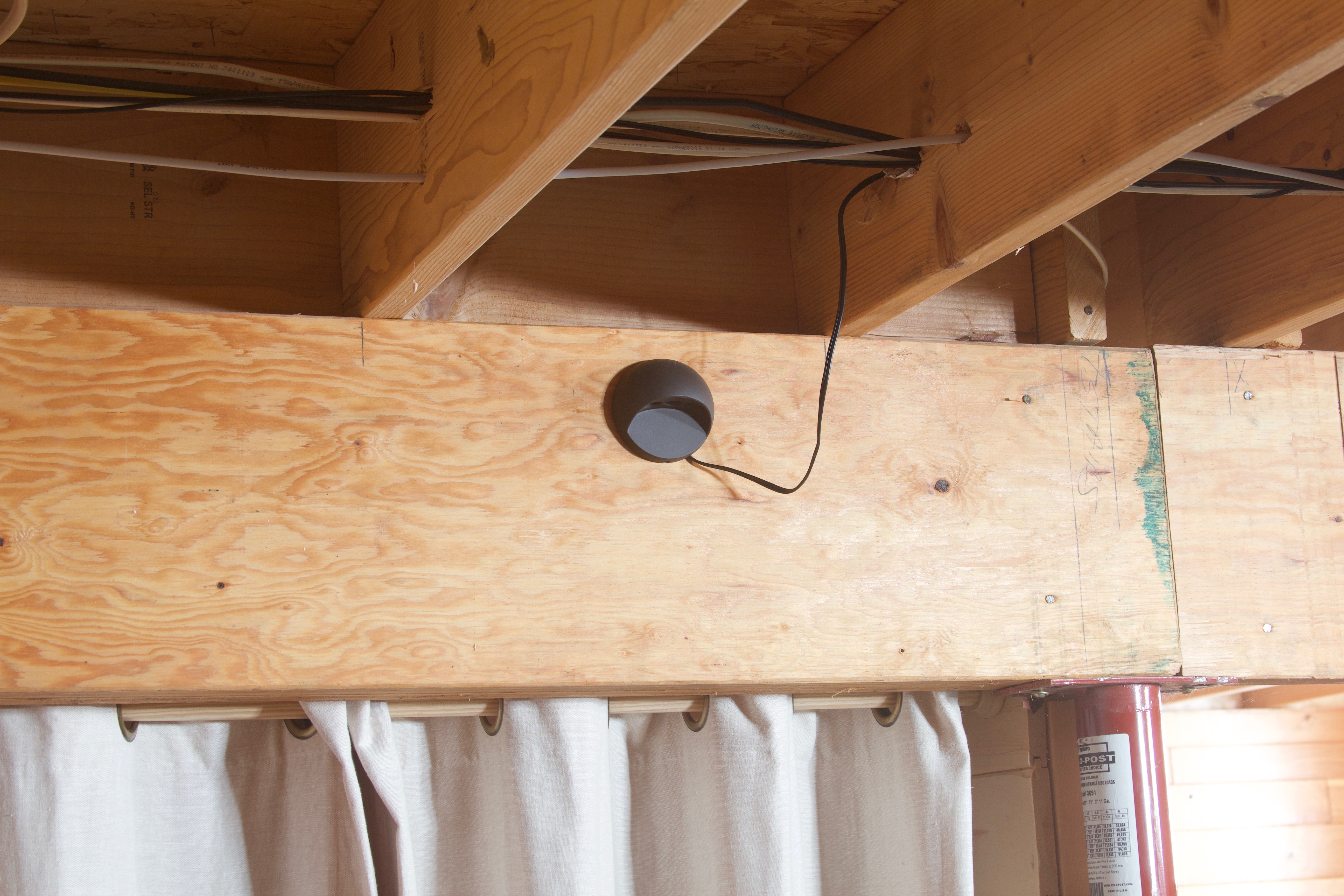
night lights
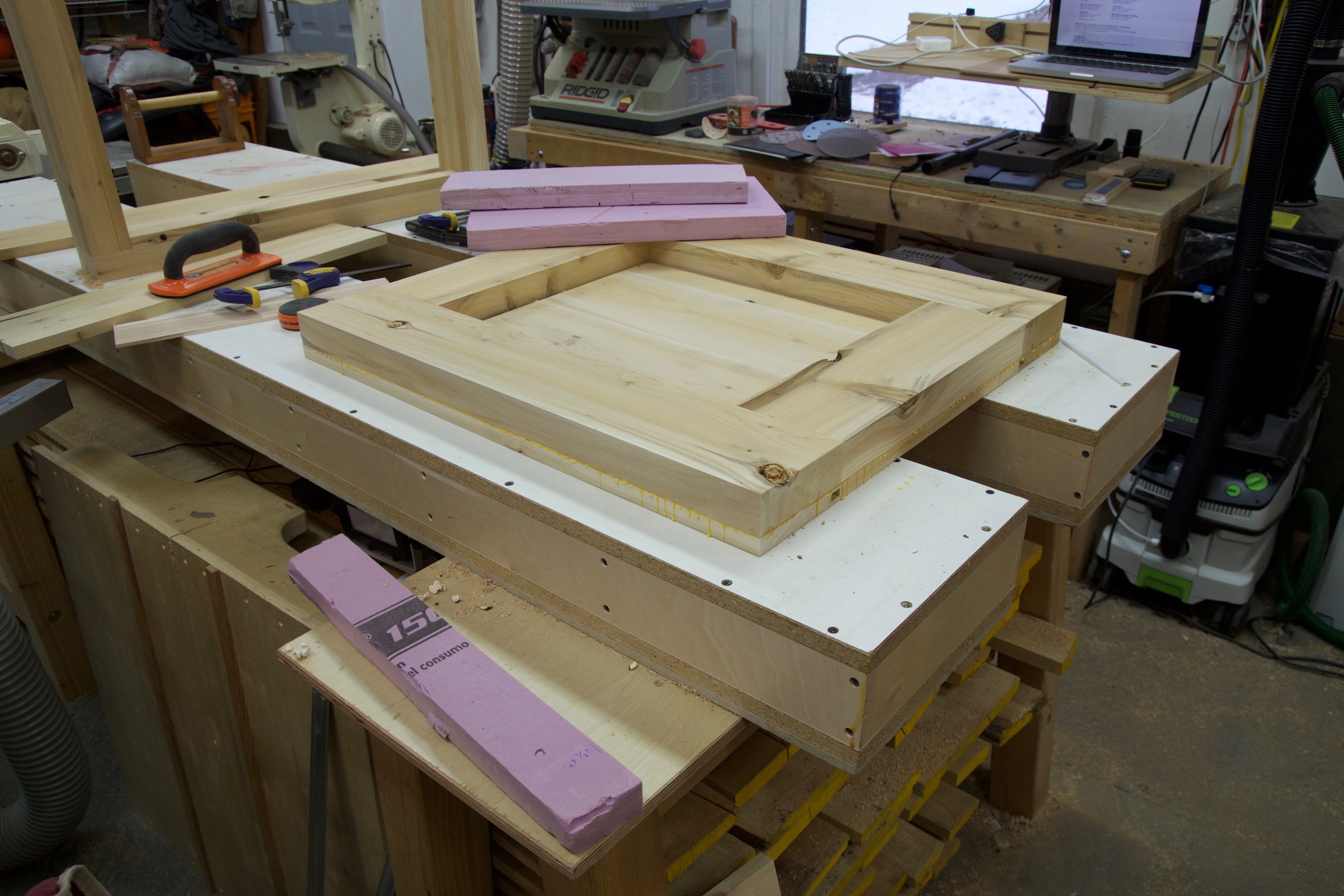
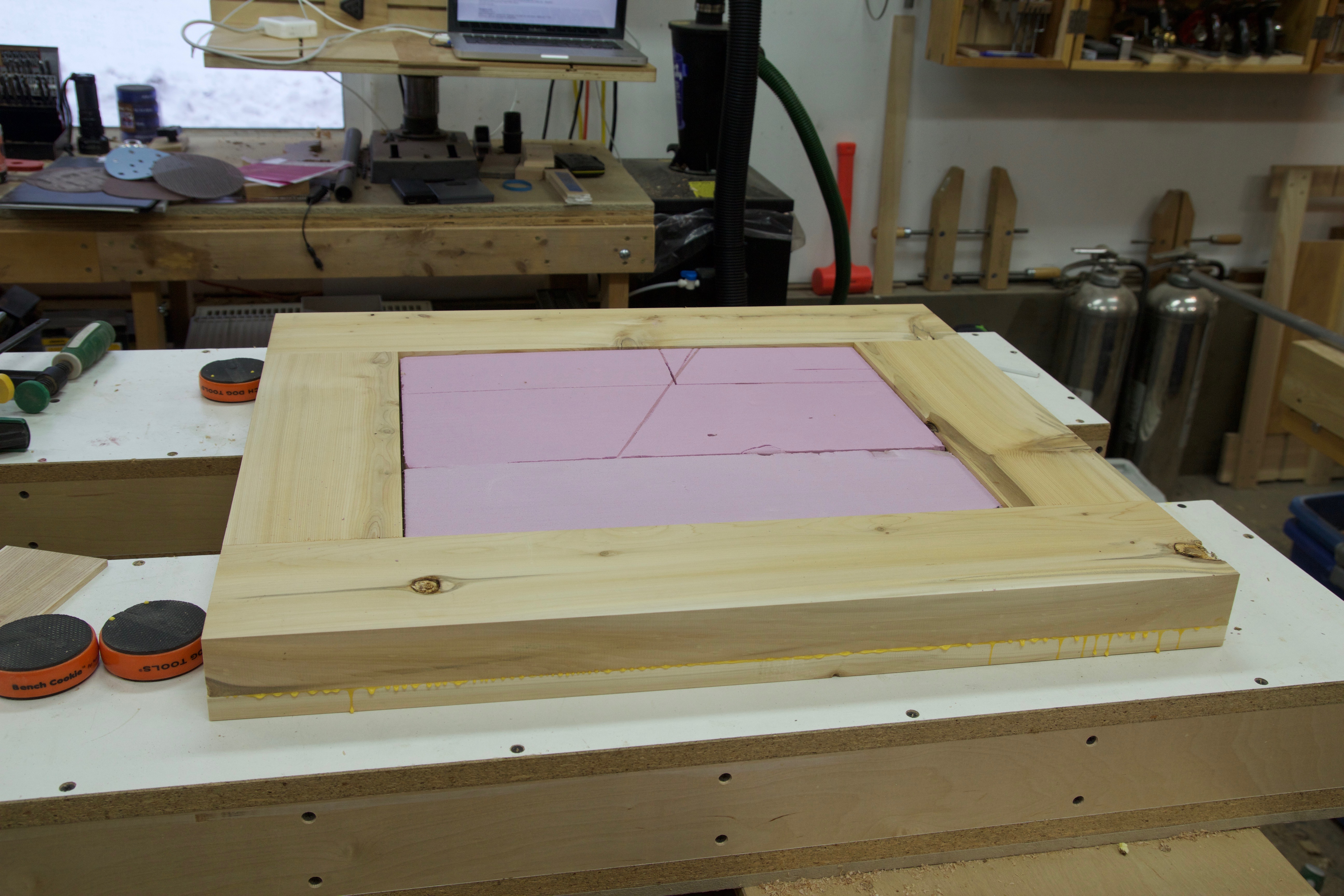
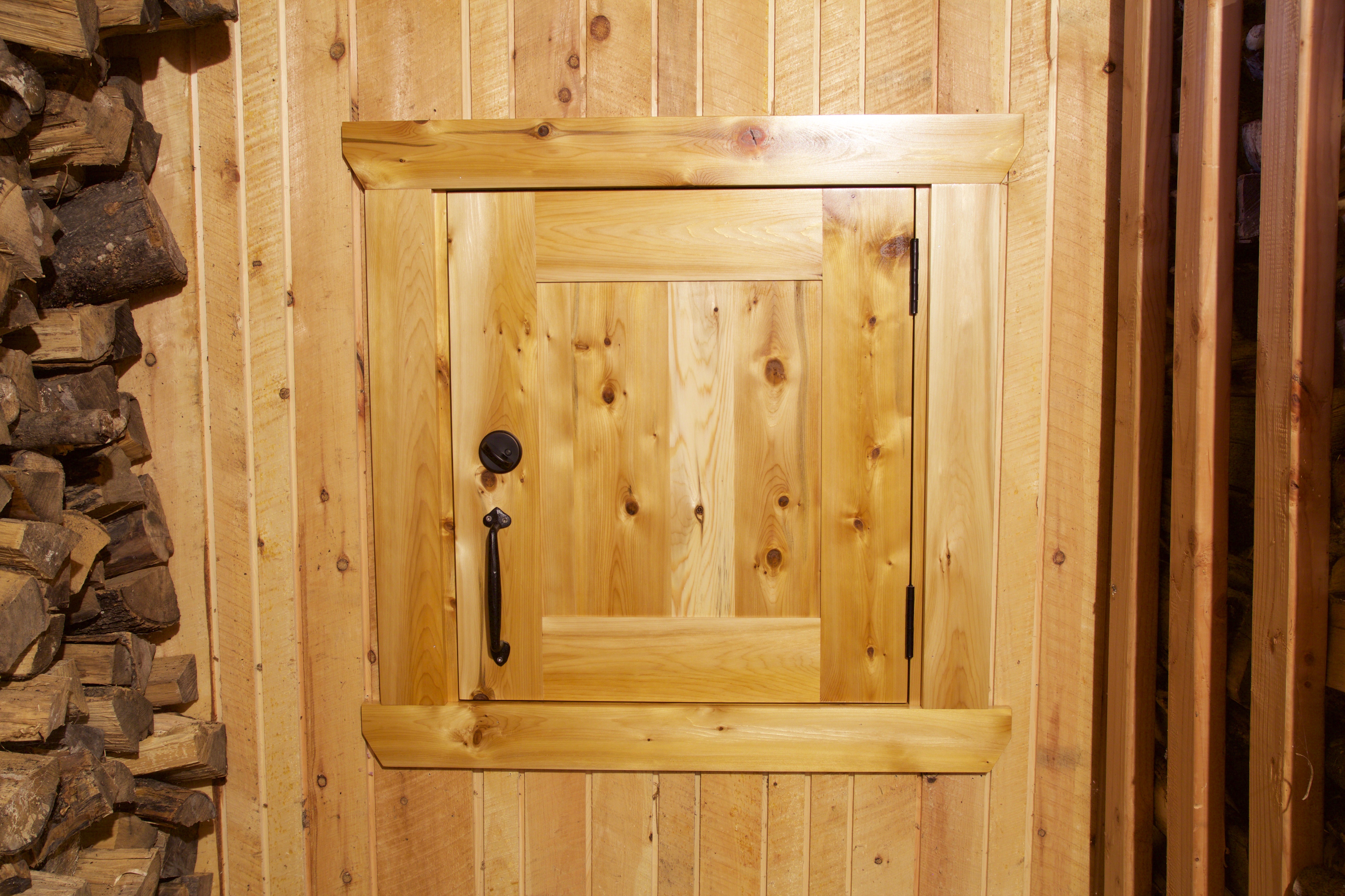
I decided to start with the egress door. The current door was treated plywood and two by fours. And it was screwed shut. The extra step of finding a cordless drill and bit while attempting a hasty escape was not quite appropriate for small children. Fall 2017 saw three new additions to my wood shop: Festool Domino XL, CT26 Vac, and ETS-150EC sander. This was the perfect test project to familiarize myself with these new tools.
The first step was to build the frame for the opening. Next the door would be built to fit. The Domino XL makes mortises for loose tenons. The frame is held together with large 14mm x 75mm beech tenons. The door is made with an outside frame and panel and an inside frame and panel with foam insulation sandwiched in between the two panels.
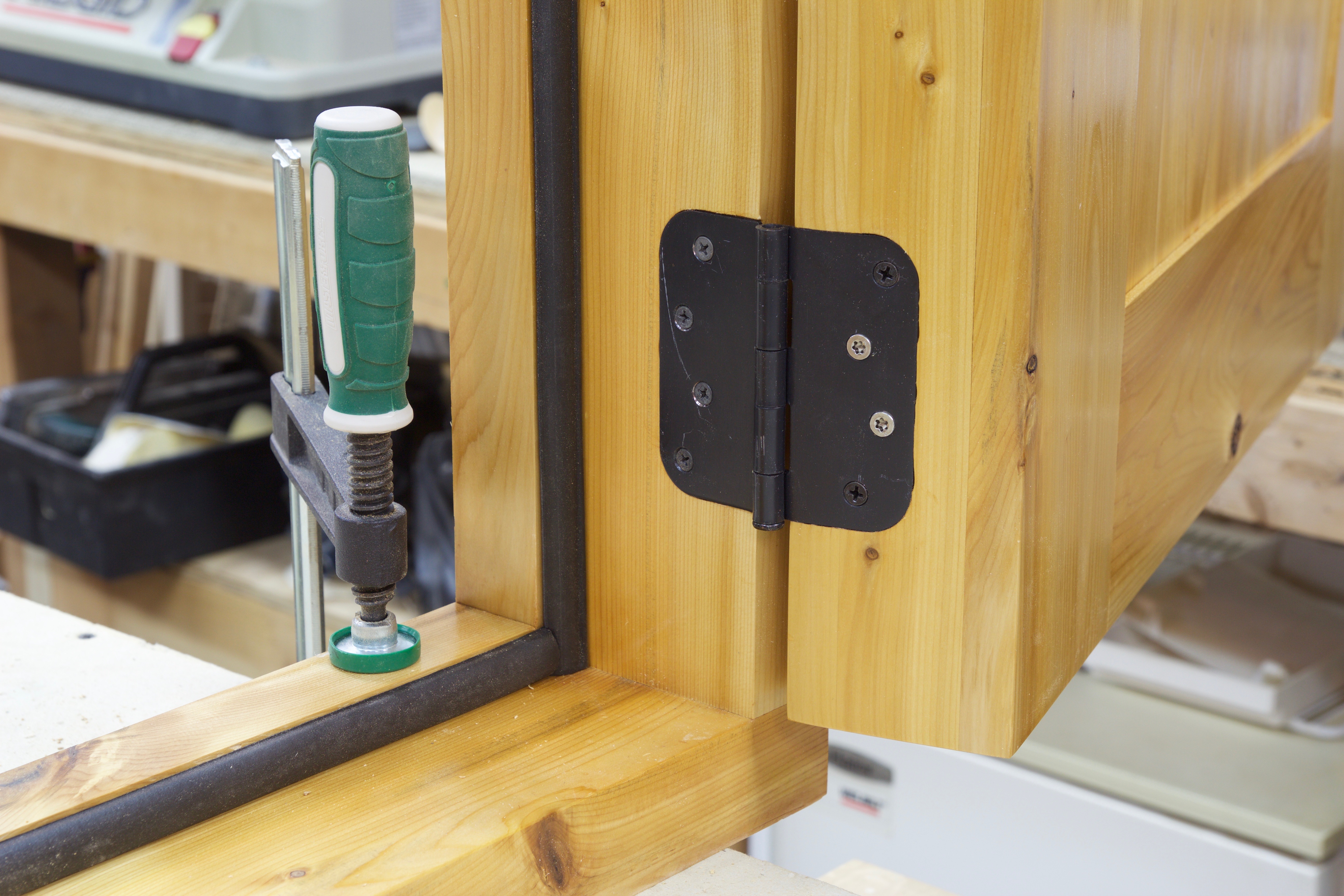
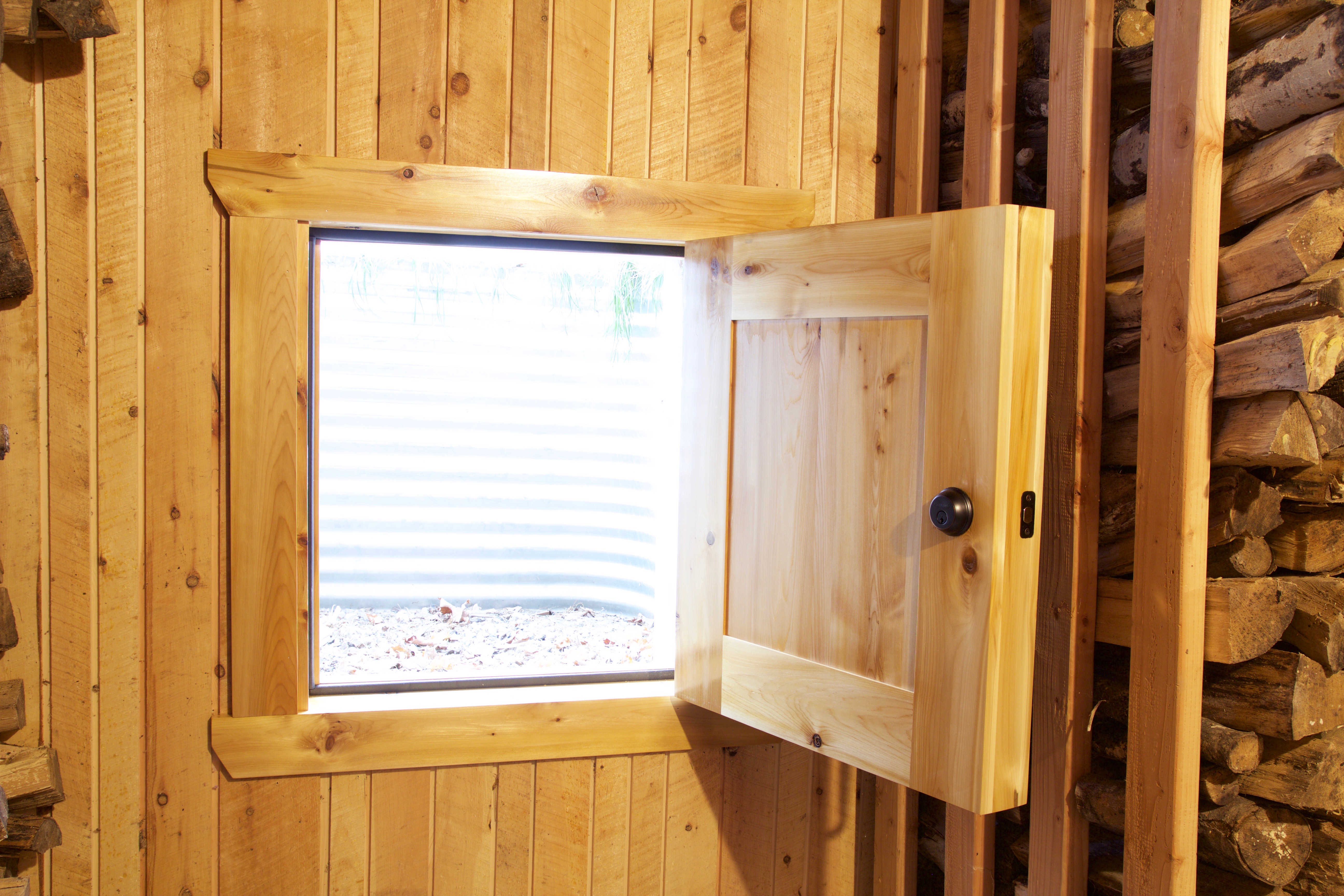
The door frame is almost 6″ deep and has a sill encompassing the opening with a thick foam D-seal making a nearly airtight seal when the door is closed. The two stainless steel screws are overkill. They are 4-1/2″ long and provide extra strength, because why not?
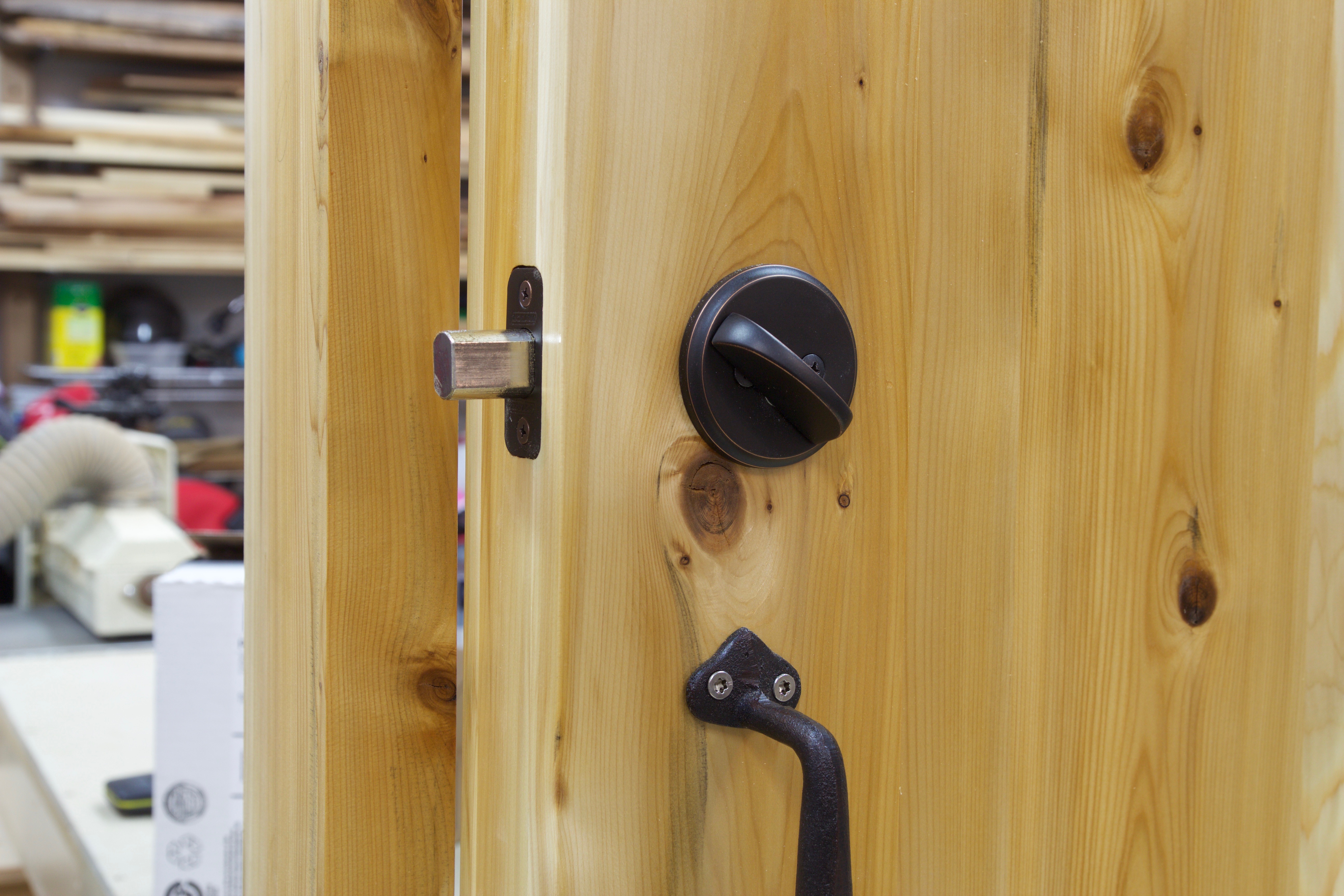
My two older kiddos are very proficient with deadbolts and influenced the design of this door. I’ve been locked out of my own house on several occasions thanks to the deadbolts on our doors. Apparently this is funny. I disagree. Anyway, it made sense to use a deadbolt as a latch for the door. Because the door is nearly 3-1/2″ thick a deadbolt extension kit was ordered and I rekeyed the lock to match the cabin door locks removing the need for an extra key. The door handle is wrought iron and was purchased at a nearby garden center. The mating deadbolt striker plate was secured to the structure using 3″ stainless screws during final installation.
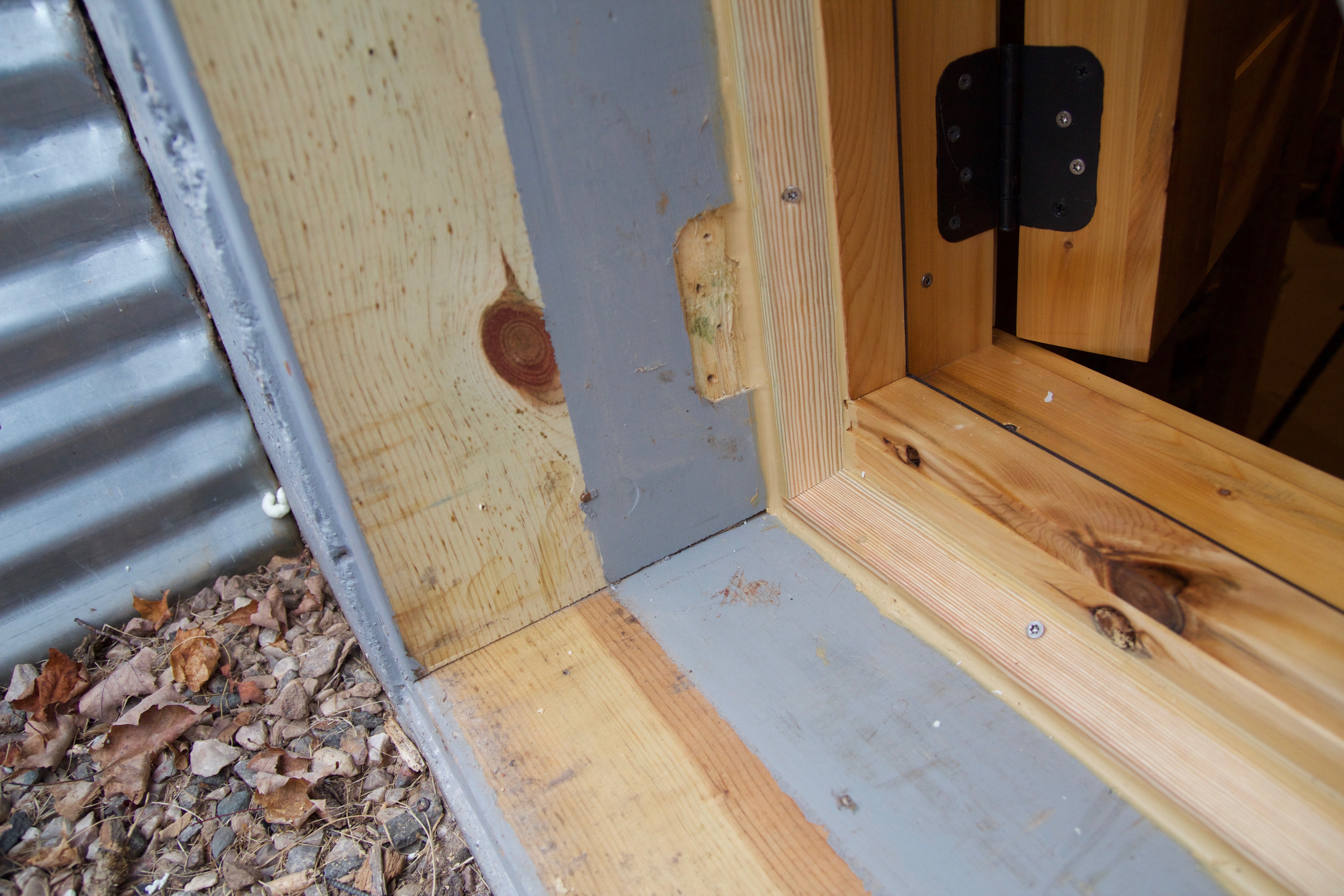
The last step before installation was to precut interior trim to match the cabin aesthetic and prepare some exterior trim from treated lumber that would be cut to fit during installation. The install went smoothly and was finished on Nov 18, 2017. I used sturdy 3″ stainless steel screws for the entirety of the installation and sealed everything with the same caulk used to seal the cracks between logs on the rest of the cabin (it’s some durable stuff). The bare pine, uncovered when the old door was removed, was later painted grey.
The finished installation is clean. It matches the rough shiplap siding nicely and the wrought iron handle strikes the wood rack, protecting the door from damage. In front of the egress is a small tub that makes a good step for a small child. Both older kiddos were asked to open and exit the door without any prior training or demonstration and succeeded without any issue.
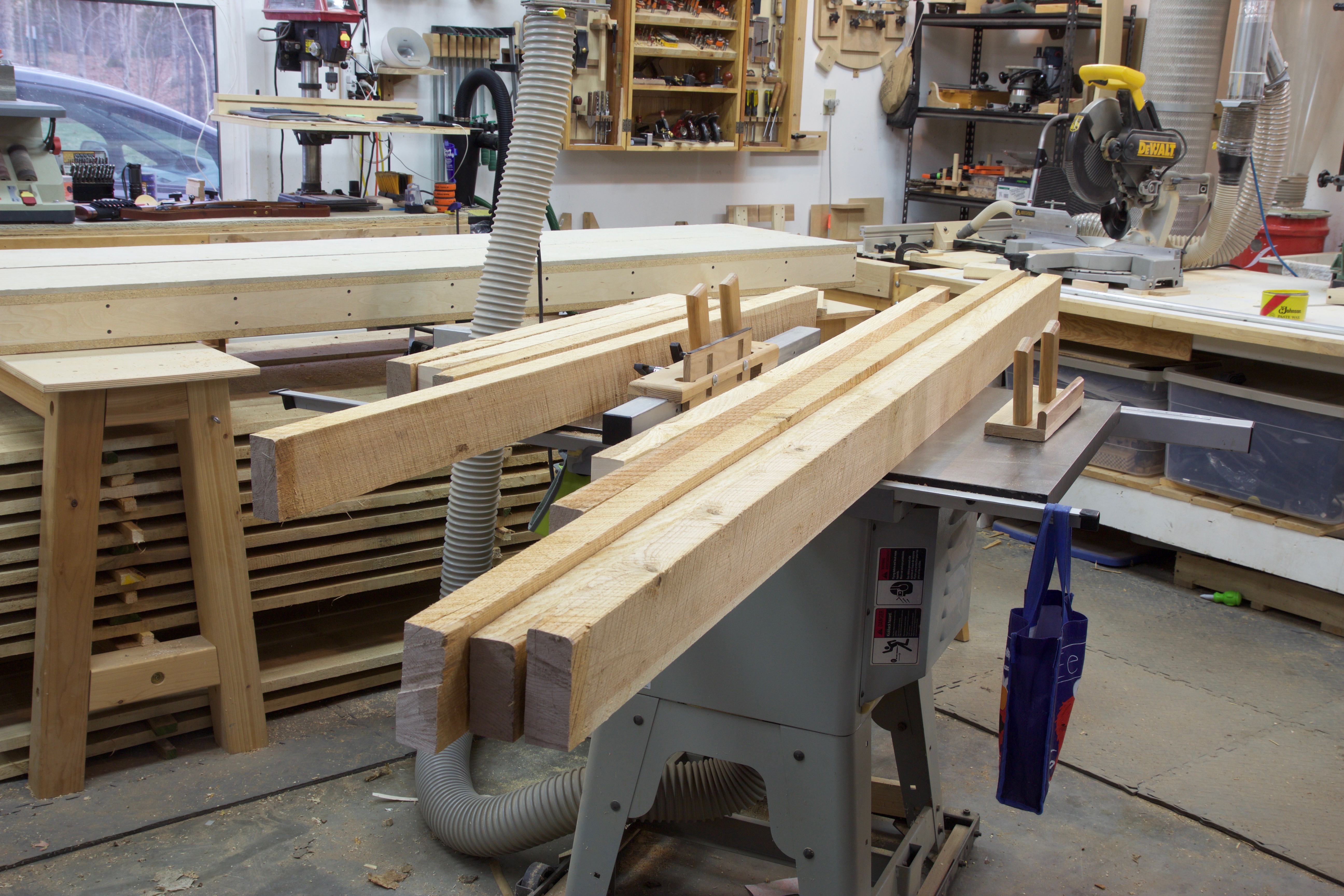
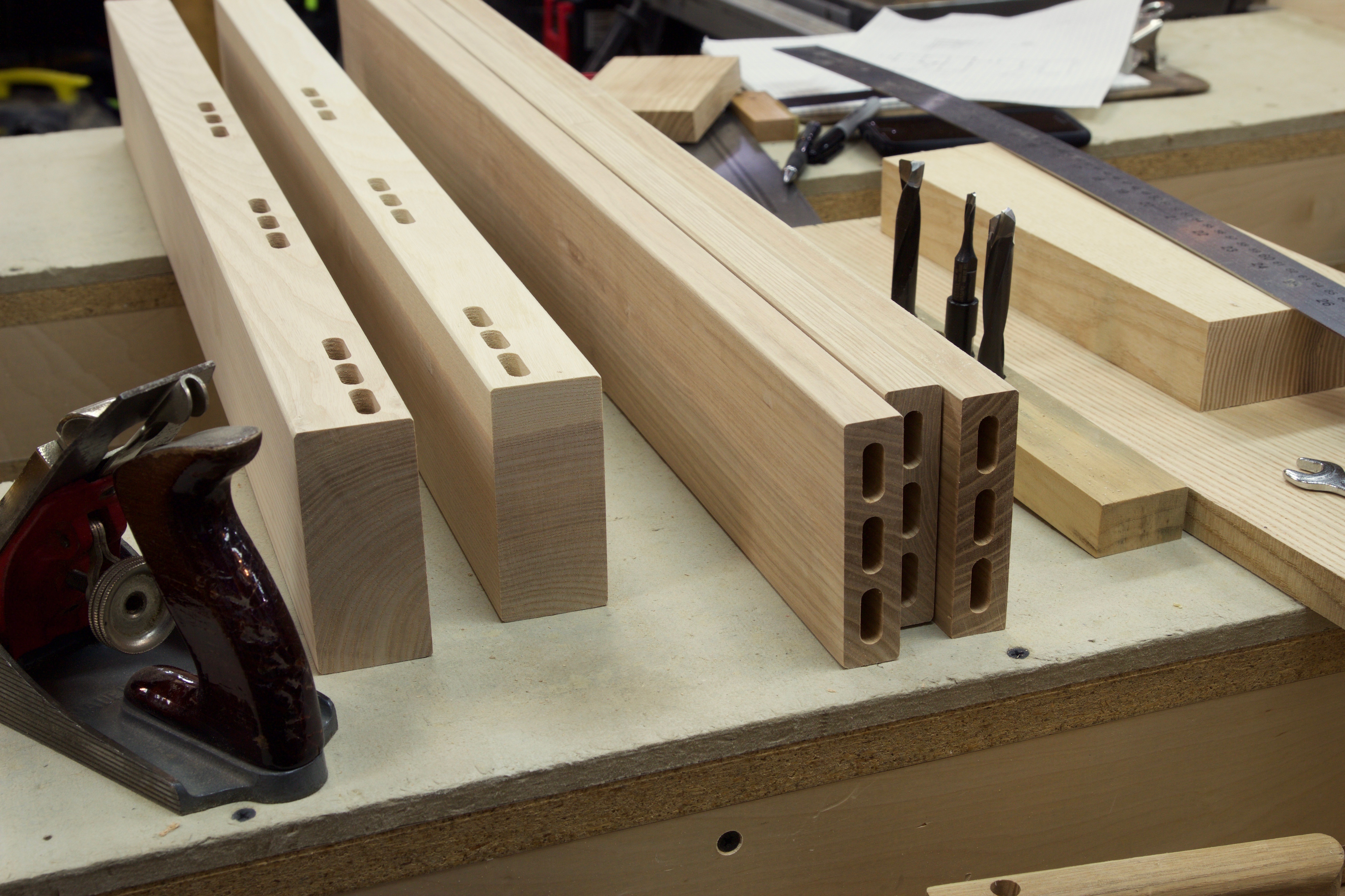
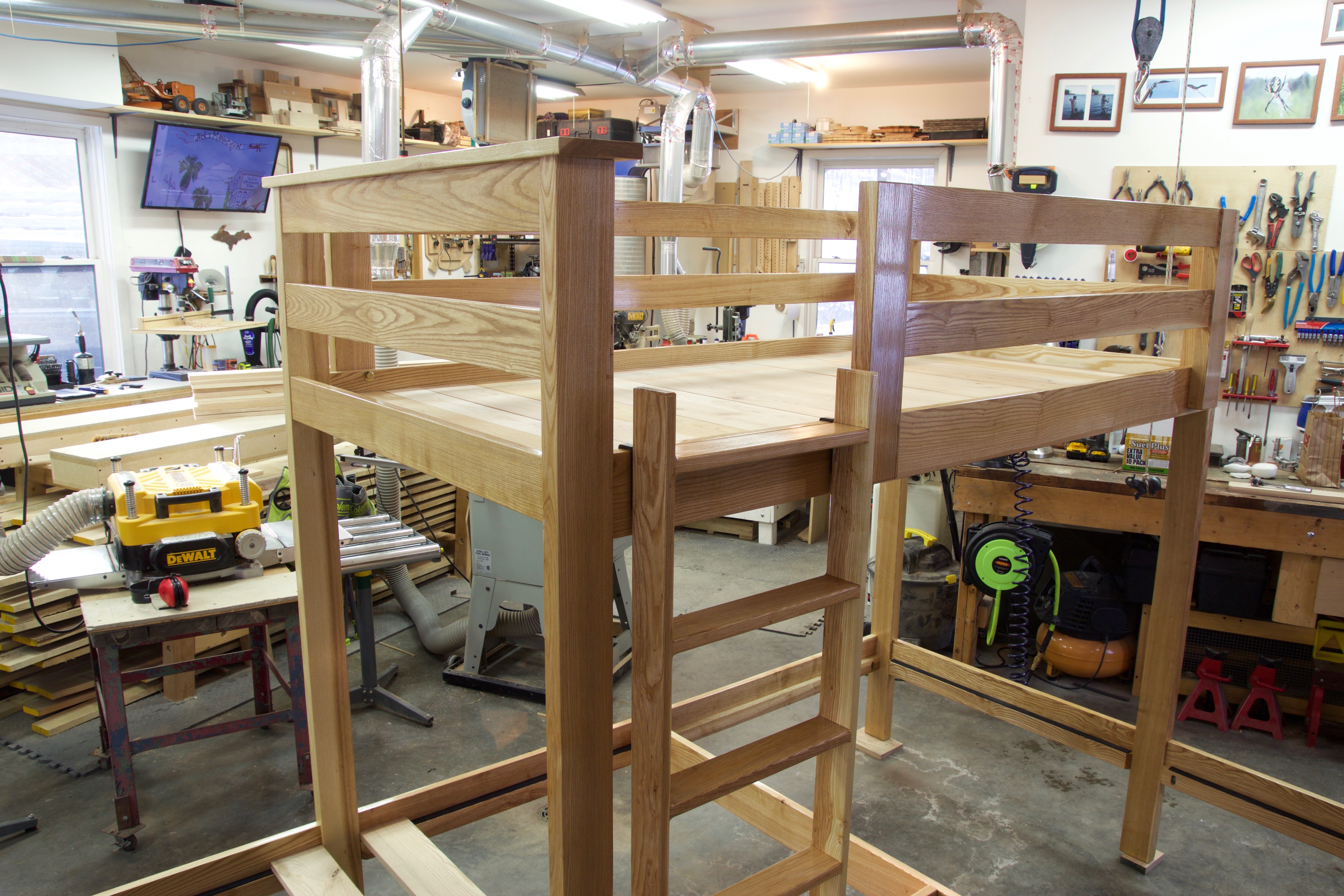
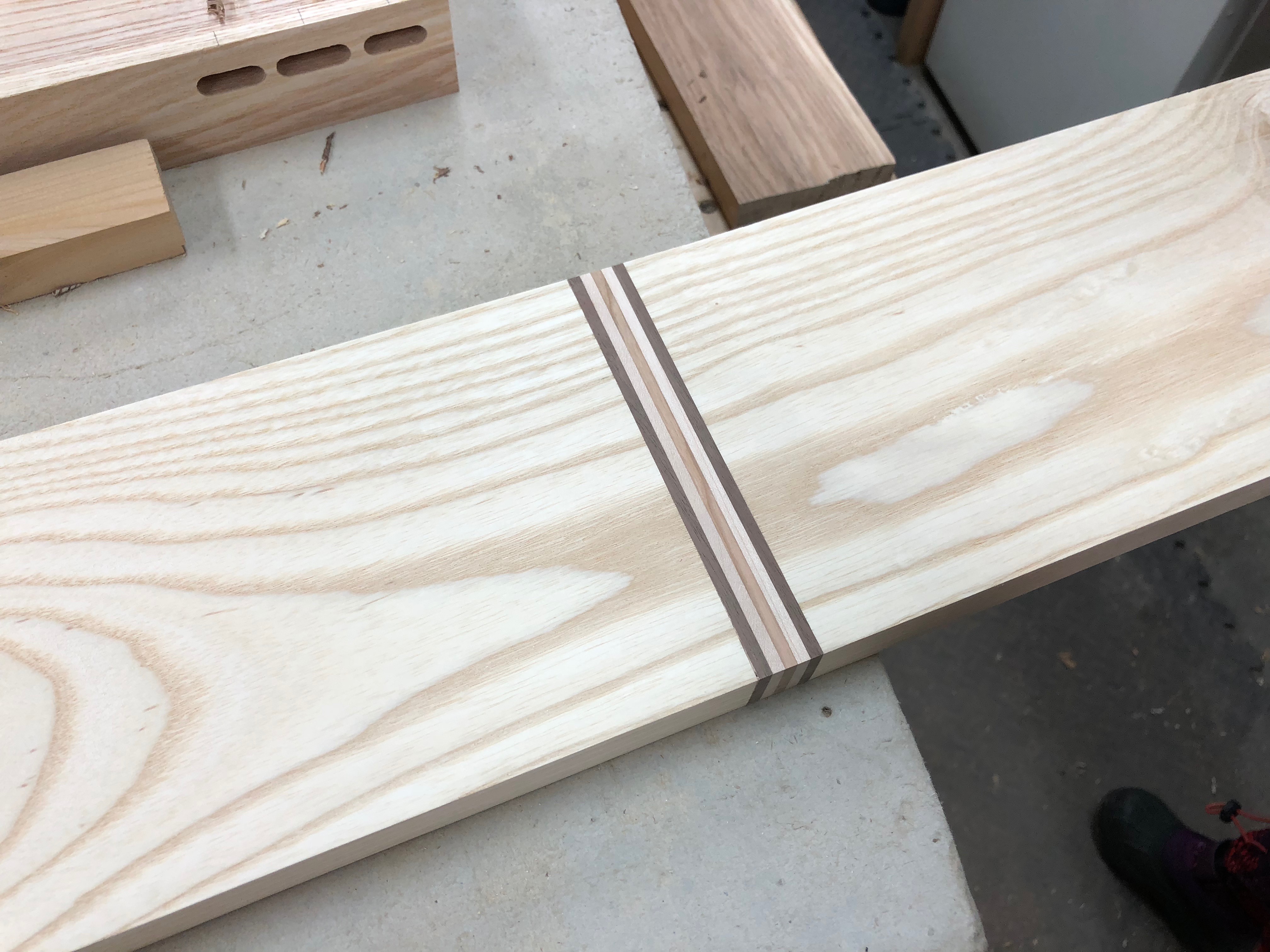
On to the bed next. I started in Late November and finished in early January 2018. I started with some gorgeous kiln dried quarter sawn 8/4 white ash sawn from the home forty. The wood was a pleasure to work with. I really had to hunt to find wood that wasn’t clear of knots and defects.
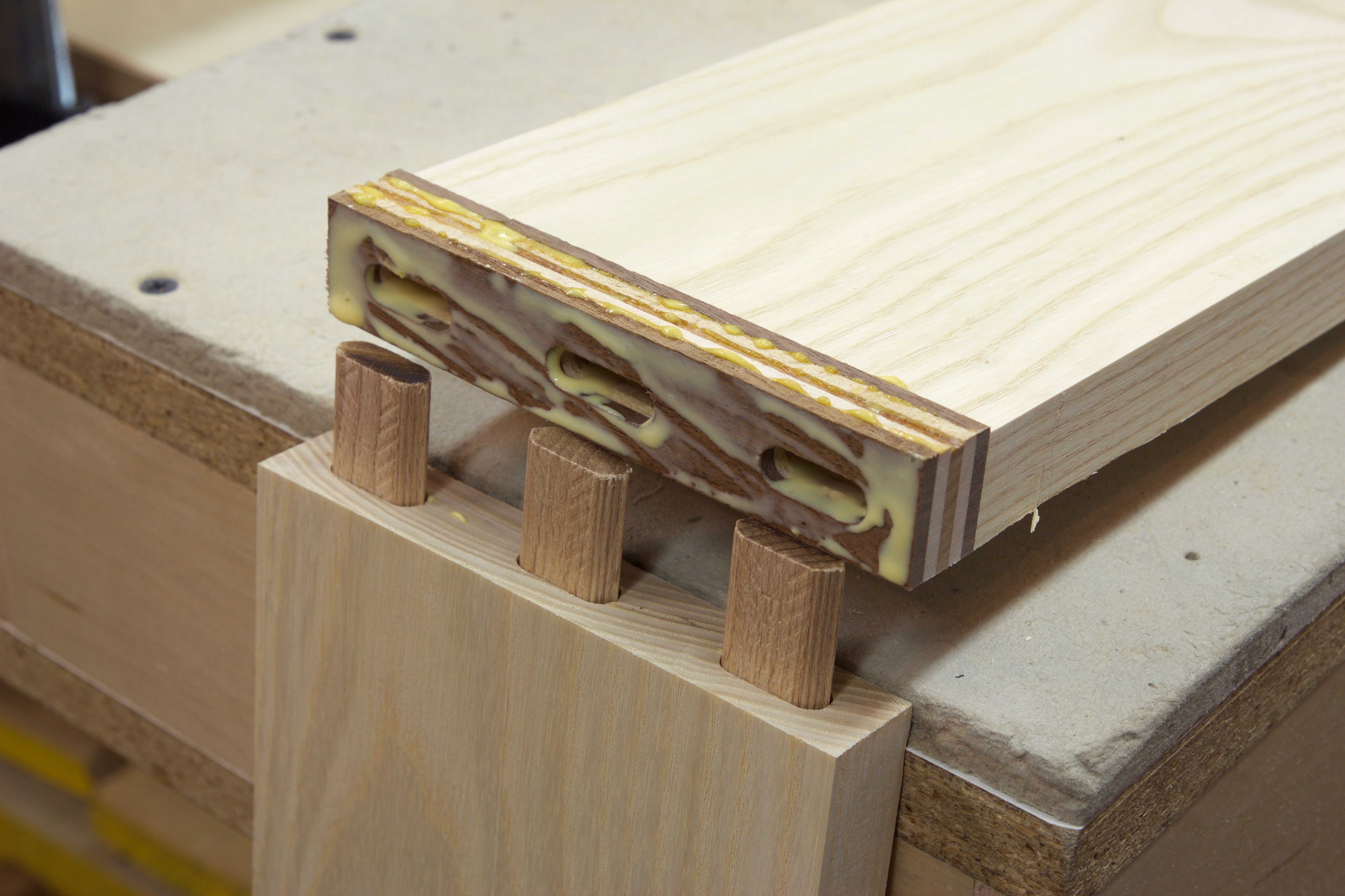
Once again, this project relied heavily on the Festool Domino XL.
The project went smoothly but took a bit of time. There were many measurements that were double checked along the way. Designing on the fly with this many measurements was mentally taxing. When the bed was assembled in the basement we had about 1″ of clearance between the walls.
Can you find my apprentice mark? I cut a headboard sill too short and spliced it back together with a decorative touch. Who says you can’t cut a board longer? If you are scratching your head at how that could possibly be a sturdy joint see the second photo. It’s reinforced with three dominos (loose tenons).
Part of the difficulty in designing the bed was figuring out how to make it disassemble and reassemble. It’s a fairly complex set of operations. Have a look.
Just fits! I… er… planned it that way 🙂
I supplied the mattresses and waterproof mattress covers. The mattresses are Linenspa 8″ Memory foam and innerspring hybrid mattresses. They arrived in a vacuum sealed bag. Once the bag is punctured watch out, they expand! At $84 a mattress they will get used maybe 30 times a year and are just as good as the $400 pillow-top mattresses on the kiddos’ bunk beds at home. My mom provided sheets, pillow cases, and comforter, and even a quilt for each kiddo (not pictured).
One later modification was to bolt the ladder to the guard rail (thanks Wood Whisperer Thread Taps). I learned the hard way that a good yank with the right hand on the upper guard rail will torque the support rail something fierce and put too much stress on the domino connector joinery system. No permanent damage was done in uncovering this flaw.
When it comes to fire safety there are two products I endorse without reservation: Nest Protect smoke alarms and Ansul fire extinguishers. They are each best in class products. I will only ever buy fire extinguishers with all-metal parts and smoke alarms with the ability to detect BOTH fast-flaming fires AND smoldering fires coupled with carbon monoxide detection. The Nest smoke alarms are pricey but with the ability to connect over the internet to a smart phone, remind you when to replace batteries, run system checks monthly, detect fire via combination ionization and photoelectric sensors, and wirelessly interconnect (even between buildings) I can’t find a better device.
And finally, a night light. A double light switch at the bottom of the stairs was added. One switch controls a 12VDC 400 lumen LED bulb in front of the egress door and the other controls a 12VDC LED path light that has been adapted as a night light. The night light is temporarily mounted in the ceiling. Another suitable nightlight I just discovered is 12V accessory lighting for vehicles. There is a huge selection of brightnesses and colors available.
I’ve slept in the basement and it’s really comfortable! The flicker from the propane fire dances on the opposite side of the room. The 12V night light casts a gentle warmth along the side of the pool table. The mattress is soft and the heavy blankets are cool and feel secure. The glass block windows along the top of the wall ripple like water in the moonlight. In the morning the sun slowly filters in and floods the basement in the warm optimism of a winter morning. It’s no wonder the kiddos love spending the night… or it could just be because we make big breakfasts.