
11.11.2021 – Thursday
Today the cabin saw a new battery bank officially enter service! But first, a brief reflection on the first battery bank and its years of reliable service.
The original flooded lead acid (FLA) battery bank, made up of 14 golf cart batteries, lasted for 12 years and 500-700 cycles. At the beginning it was capable of 1540Ah at 12V and weighed in at 860 lbs. The longevity of FLA batteries is commonly accepted as 500 cycles or about 5 years for high quality cells. The cabin had Sam’s Club batteries manufactured by Johnson Controls. They were pretty run of the mill. The one advantage we had was a solid maintenance schedule and we used only the top half of the battery capacity, operating between 100% and 50% state of charge (SOC).
The Ol’man was in charge of watering the batteries. As they charge and discharge, some of the water is lost as hydrogen and oxygen gas (remember the copper passive vent pipe in the battery box – it served us well). Over the years the need to water the batteries began to increase. It was a rare event for the first 5-7 years, then started to become twice a year, then finally ending at every 2 months. Along those same lines, the capacity started to decline slowly, then at year 9-10 it was noticeable. In the last 6-8 months it was abundantly obvious the bank was in a death spiral. We had maybe 150Ah of capacity before the system was at risk of unexpected shutdown from low voltage when a medium sized appliance requested power.
Goodbye battery bank 1.0 and thank you for 12 years of service.

Hello battery bank 2.0! I think it’s fair to say, it is sexy! – aluminum cases, bluetooth, over temperature and under temperature protection, overcurrent protection, thermostatically controlled low temperature warmer, and at less than 1/4 the weight.

The process of adopting a new chemistry required new knowledge. The internet is vastly more powerful at distributing knowledge compared to 12 years ago. There is a video for everything and a thousand comments for each video. Channels on Youtube are built around specific disciplines and span from casual to highly technical (yay!). When I started over 12 years ago, I stumbled awkwardly around forums and read manufacturer installation manuals front to back, stopping to research new terms as I encountered them. It proved a successful strategy, but wow, was it time consuming. This go around I managed the preliminary research and basic design of the pack in about 4 hours. From there I selected and researched specific components, another 2 hours. Orders were placed in early October and in one month I had a bench full of components!
I need a moment to give credit where credit is due. Off-Grid Garage on YouTube put together a lovely video with lots of delicious technical details and test results of the exact cells I purchased. Best of all, he listed downloads of the data he pulled from the testing on his website! I love data.
I also spent a lot of time on DIY Solar Power with Will Powers on YouTube and his corresponding website and forum. The DIY Solar Power Forum is a trove of good information (the resources tab was particularly useful). His videos introduced me to Overkill Solar BMS and helped me settle on the overall design of battery bank 2.0
Hardware time. After some back and forth the Ol’man and I arrived at a plan for battery bank 2.0. Here is the complete parts list for the project.

Once I built out the order list I took a moment to look up some alternatives to confirm that building the battery from the cell up was the best choice. SOK was the prime alternative for the stationary battery bank I had in mind. I also included two other batteries that have competitive technology. The SOK has prismatic cells like the battery bank I built, Renogy uses pouch cells like in cell phones and the new generation of power tool battery packs, and Battle Born uses cylindrical cells like electric cars and has a built in battery warmer for low temperature operation.

I assembled one more chart before purchasing the components. The main objective of this chart was to see just what $4300 could get from each of the four options above.

Confident with the decision to build, orders were placed. Everything arrived without issue, with the cells arriving last on November 9, 2021. The same day the cells arrived I stayed up late building the battery bank. I called it a night at 2am after powering on the BMS and verifying the cells were balanced and matched as advertised. Well done http://www.solarsupplyhouse.com – you guys delivered some top notch EVE 304Ah LiFePO4 cells with bus bars and nuts, making my life much easier. The Overkill Solar BMS were also extremely easy to connect to over bluetooth on my iPhone and very well built.
Building the pack to live in an insulated, but unheated garage was the first technical challenge. The cells are encased in an aluminum shell and should conduct heat fairly well. Starting with a large 1/4″ thick aluminum plate I added an adhesive heater pad to the underside. The heater pad I used was the Facon CW-T1218, which is 12″ x 18″ with a 3mm foam pad that covers the heating elements and wiring. The adhesive is quite strong and I am certain it will not fail with time. When active, 4.8A at 13.5V provides 65W of heat to the aluminum base plate, which in turn transfers heat to the cells. While the heater pad is automatic, turning on at 45°F ( ± 5 degrees) and off at 68°F( ± 5 degrees) I wanted more specific control, and added a 12V thermostat. The thermostat is from Inkbird and set to turn on at 40°F and off at 43°F. Four hockey pucks (handy for so many projects) keep 200 lbs of battery from crushing the heater pad and are attached with permanent mounting tape.

The next major component to unbox and prep was the Overkill Solar BMS. This battery management system for 12V batteries is an impressive unit. I selected it because the manual provided is extremely thorough and has just enough sarcastic wit throughout that I enjoyed reading it:
Whatever stupid thing you do with our products after you buy them is 100% on you. There is no way to make them completely safe. We support you learning new things through research and experimentation, but a certain baseline level of technical competence and sound judgement is absolutely required. If you are completely confident in your abilities, turn back now. Fear keeps you alive
OverKill Solar BMS Instruction Manuel

Overkill Solar also tests their product before shipping. Confident I would not amputate any fingers or otherwise harm myself I continued on…
I quickly realized that I was a bit short on bus bars. The only suitable conductor I had on hand was brass. Brass is not ideal, coming in at 28% the conductive capacity as tinned copper. Brass is, however, workable with woodworking tools. I fabricated 12 brass buss bars and doubled them up so they would be roughly 4x the cross sectional area as the tinned copper buss bars included with the batteries. The studs on the cells had just enough thread to accept my home-made bus bars double stacked. Thank goodness for a well stocked shop.

Next, I crimped and soldered ring terminals on to the balance wires of the BMS. I am fast becoming a fan of using solder in as many electrical applications as possible. Soldering is cheap, easy, and highly effective at preventing issues down the road. Soldered ring terminals will never come loose from the wire whereas a simple mechanical crimp could face issues from temperature fluctuations or vibration.


Using polyimide tape I assembled the cells into groups of 4 and then into a single pack of 16. A quick and dirty wiring test proved that everything worked. The BMS checked out and the cells were indeed matched. The official “it’s alive” screen capture from my iPhone after connecting over bluetooth to the BMS. Yeah… that’s 1:34am and 2:05am… this is the exact charge state of the batteries just hours after delivery.


Electrical tape, zip ties, double sided permanent mounting tape…
Soon the battery pack was in its finished form. Even the thermostat for the battery heater pad was wired in (it’s also fuse protected).

I then got some sleep. More would have been better… but some was enough.
11.11.2021 – Thursday
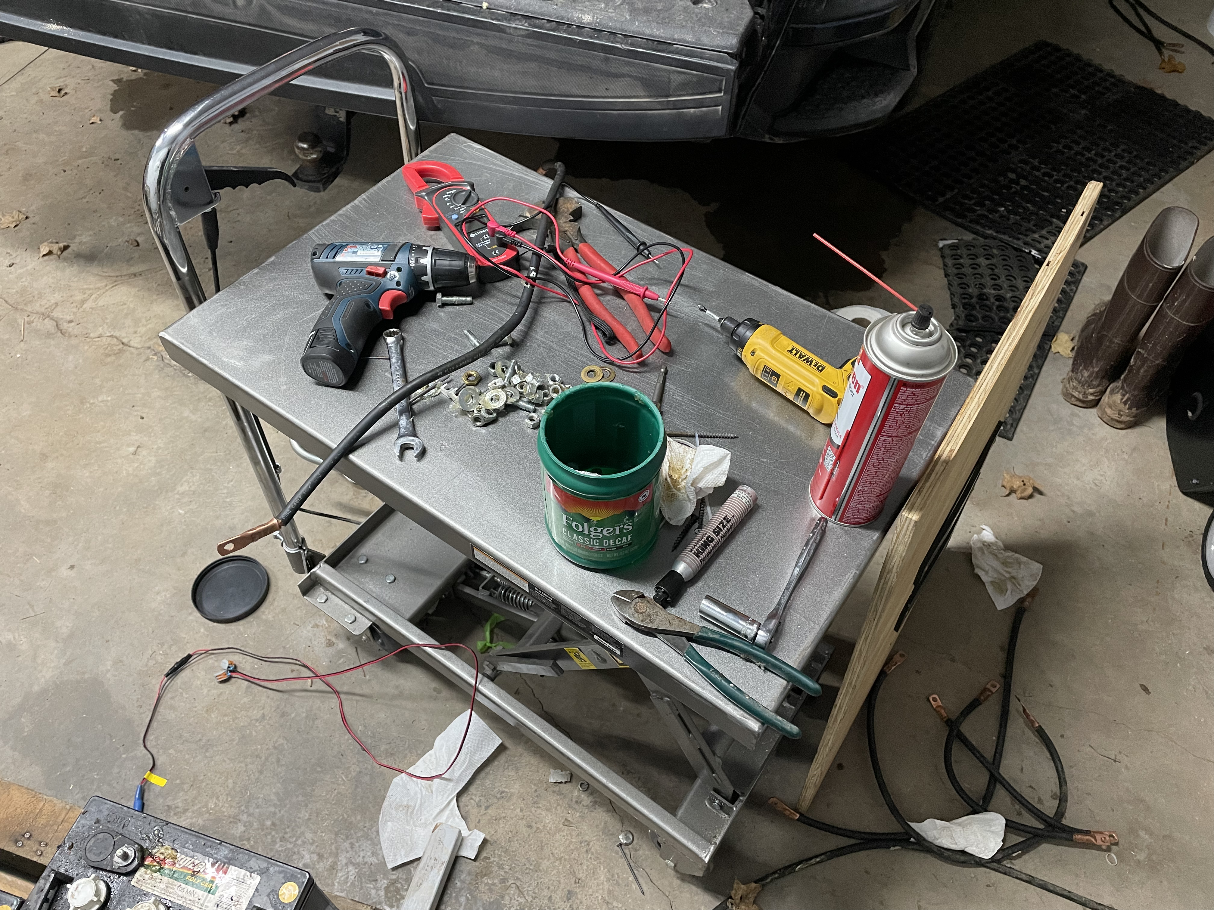
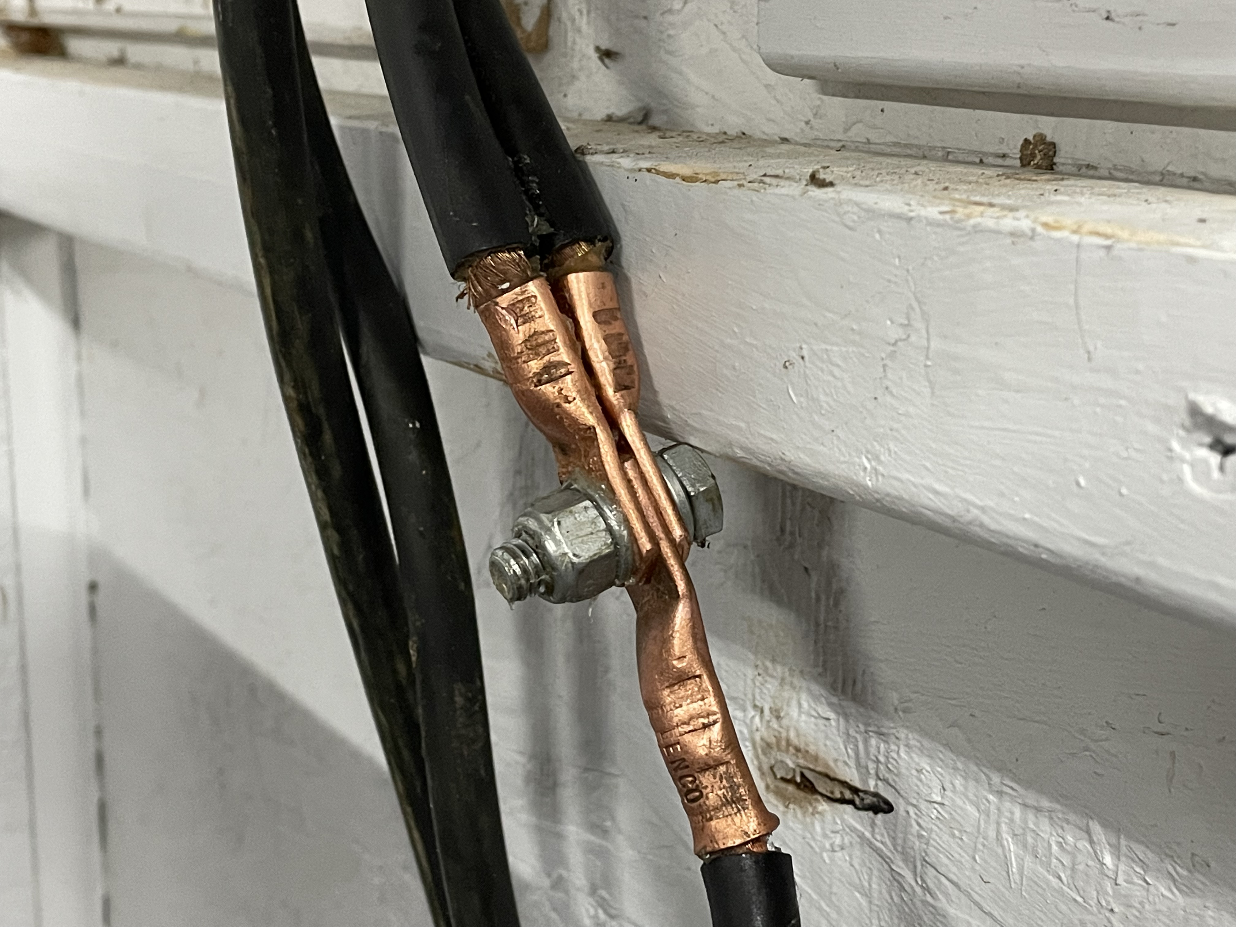
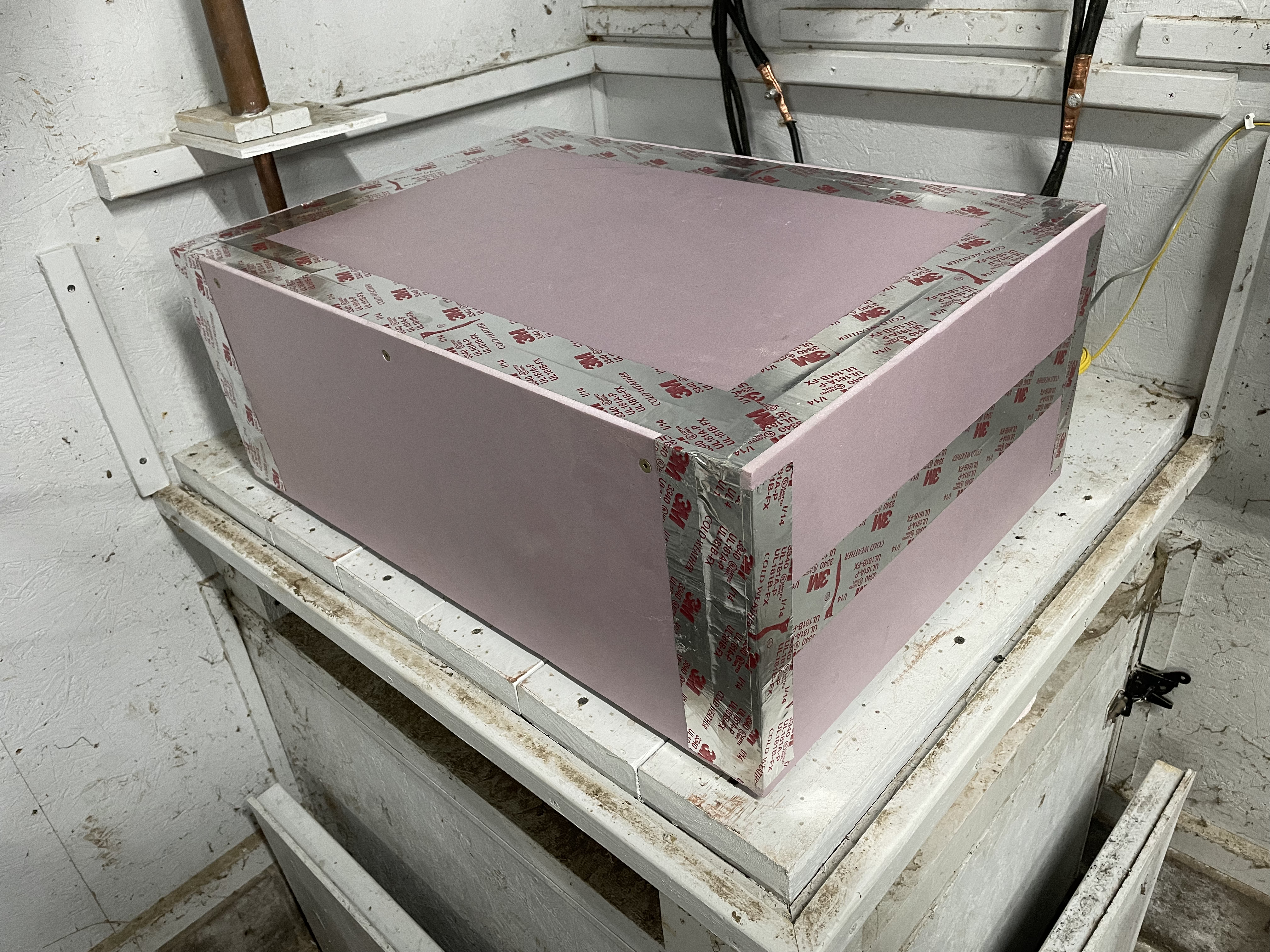
Figuring out how to transport the finished pack was a bit of a mind-bender; the aluminum base plate is not very tractive against the mating surface of the aluminum LiFePO4 cells. Let’s simply say that the solution was provided through the creative use of plywood, a rubber mat, and two ratchet straps. At camp I was able to slide the pack off the truck tailgate onto a lift table and slide it over to the battery platform in the garage. I cleaned and then reused the battery cables from the old battery bank and after two hours got things connected and properly torqued. A few cable were short of the required length to reach the buss bars on the wall. I doubled up and did my best to match the length of the four battery cables that connected the pack to the buss bars. A final touch was the addition of a styrofoam box with a 1.5″ wall thickness. It was assembled with construction adhesive, a few long wood screws, and metal HVAC tape and will be a winter-only accessory.
11.12.2021 – Friday
Is that smoke?
I learned something valuable today. Don’t buy electrical parts that are not UL listed (except for the Overkill BMS) because they will try to burn your off-grid garage down. A properly constructed off-grid system will defend against a failed component and should not burn down. That was the case this evening when I entered the garage and questioned why there was an odd smokey plastic smell. Not one to turn away from anything out of the ordinary, I investigated and discovered the issue. This (claimed) 500amp battery disconnect switch is complete garbage. It was purchased from amazon.com and was a ticking time bomb. Under a two hour sustained 130 A load (charging the batteries) it self-destructed. The undersized conductor burned right through and melted the plastic shielding.


After this surprise, the switch was deleted and progress continued adapting the off-grid system to the new battery bank. After reviewing some reference material and discharging and then charging the battery bank I was able to establish some settings that will work with this specific battery bank and our Xantrex SW3000 12V Inverter/Charger. The Inverter will cut out at a low voltage that leaves about 15-20% SOC in the batteries and high voltage cut out under charge will stop around 90% SOC. Operating in this sweet spot provides about 10KWh of power and allows for an estimated 5000 charge cycles and 30 year lifespan for the batteries.
Up for a three day weekend before the gun deer season began November 15, I began programming the new Off-grid cabin system settings into the BMS, inverter, and solar charge controller. After doing some research online I consulted some excellent charge/discharge charts from Youtube channel Off-Grid Garage and programmed the protection and capacity settings for the BMS. After that I began to discharge the batteries, stepping down the low-voltage cut off for the inverter until I was fairly confident I was sitting around 17.5% SOC and settled on 12.7V as the low battery cut off set point for the Inverter. Since batteries will experience a voltage drop under heavy discharge, I set a 6 minute delay so the system must read 12.7V without interruption for 6 minutes before cutting off. This makes sure that the inverter doesn’t cut out if the well pump or microwave is used when the battery bank is close to requiring a recharge.
After reaching the low SOC point, the generator was run until 80-90% SOC was reached. The same technique was used. The charge current was set to 14.4V and the charger bulk terminate voltage was stepped up until the charger cut out around the desired 90% SOC. This setting is specific to charging at 130 A for 1216 Ah of EVE 304Ah prismatic cells because the charge current and battery internal resistance will primarily determine what the stop voltage is for 90% SOC. The inverter stopped charging at a reported 14.2V current – however, the battery BMS recorded a battery voltage of 13.70V at this same point in time. Once the battery came to rest it settled around 13.30V under a load less than 150W.
Watching voltages, consulting charts, and changing settings for three days left me with an interesting observation. Battery monitor, Inverter, and BMS all report fairly similar V under discharge. Things get more interesting under a large discharge, and are wildly different under a charge current. This is why it is important to discharge/charge, let the battery rest, test the voltage and repeat until the Inverter/Charger settings correlate to the desired operating SOC range. In this case it is 17.5-92% SOC.

I still need to set the solar charge controller to play nice and not attempt to overcharge the batteries, but for now it is set at what I think will work best. Because it charges at a much lower current (0-40A normally) I have it set to a slightly lower 14.1V bulk but kept the 13.6V float. If it’s not set just right the BMS will step in to protect the batteries against overcharging.

And now for some reference charts. These are widely regarded reference numbers for LiFePO4 batteries. Unfortunately I cannot find manufacturer charge/discharge data that is more specific than a simple pixelated graph. Below is the data from the voltage table found in every off grid forum.

I can do better though. The charts and graphs that follow are specific to 16 EVE 304Ah cells wired up into a 12V battery bank. Remember, Off Grid Garage did a capacity test and shared his data – and I love data! Using his test results I have reference numbers. I’m charging the battery bank at 130A under generator power and his test is 160A (reported as 40A per cell… 130A divided into 2 batteries with 8 cells is 32.5A per cell). Pretty dang close!


I also ran a discharge of the battery bank and set the Inverter cut-out voltage at 12.7V before running a charge cycle. Once fully charged from 17.5% to 92% SOC I recorded 925Ah, which is remarkably close to the 912Ah estimated. Error can creep in from many sources and I am trusting the BMS to count amps, but coming that close to reference is remarkable! The next step is to get the battery monitor dialed in just right. But that should be fun now that I have detailed charge/discharge profiles and data-rich BMS units collecting information and streaming it to my iPhone.


If you prefer a closer look, here is the discharge profile and the charge profile entered into a spreadsheet and graphed. For the original data files, head over to Off Grid Garage’s website.
It will be interesting to see how this battery bank performs. I was 23 when the first battery bank was installed and it lasted until I was 35. Just think, I’ll likely be retired when this one is up for replacement… whoa…


 1")
 2")


