Tag Archives: Victron BMV 600

battery monitor upgrade 2021

1.28.2021 – Thursday

My time using Victron Battery monitors is over.

A brief history:

  • July 2011: the first battery monitor was installed. A Victron BMV-600s.
  • May 2014: upgraded to a Victron BMV-702
  • January 2020: added a temperature sensor
  • January 2020: added a bluetooth module for iOS app compatibility

All along we have had several accuracy issues. The monitor would perform normally for a few hours and then it would be incredibly unreliable. Ultimately, the only useful bit of information it could report was voltage. I pored over the settings and made adjustments, updated software, and even the wiring was checked and redone. No luck.

After over 9 years my long term testing is done and I can say with certainty I would not recommend a Victron battery monitor. The two I still have aren’t for sale (or free for that matter) because I can’t in good conscious give away an inferior product that I wouldn’t use myself.

In this new post-Victron battery monitor world the Ol’man and I tried something new: a pair of generic battery monitors. The model I selected is the bayite DC 6.5-100V 0-100A LCD Display Digital Current Voltage Power Energy Meter Multimeter Ammeter Voltmeter with 100A Current Shunt from amazon.com

Specifications: 

  • Working voltage: DC 6.5 ~ 100V 
  • Measuring Accuracy: 1% 
  • Power Consumption: 0.2W 
  • Measurement speed: 2 times/s
  • The blue backlight can be turned on/off manually
  • Test Range and Display format: 
  • Active Power range: 0~10kW
  • Energy range: 0~9999kWh 
  • Voltage range: DC 6.5~100V 
  • Current range: 0~ 100A 

Pretty basic specs. I purchased two and installed them in the garage. The are affixed to the wall with that really awesome outdoor velcro made by 3M that goes by the trade name: Dual Lock Reclosable Fastener.

The top monitor records information for the 12V accessory system at the cabin (cellular booster, 12V motion lights, cabin phone charging station) and the bottom records the solar energy generated from our 810 Watts of PV array. So far after half a year of use, these two $16 monitors have proven accurate and reliable. One advantage, and something the Ol’man and I both took a liking to is the ability to see four values at one time; Volts, Amps, Watts, and Watt hours. With our previous battery monitor, only one value was visible, and manual input via a tiny stiff button was required to glimpse additional values. Here is the full user manual for these two garage battery monitors.

With the success of the two new monitors in the garage my attention was turned toward the cabin. The search for a Victron upgrade began and ended in about 30 minutes. The clear winner was a unit from Renogy and it came in around a reasonable $100. It has a much shorter User Manual than the Victron and displays all the important information at once. Specifications:

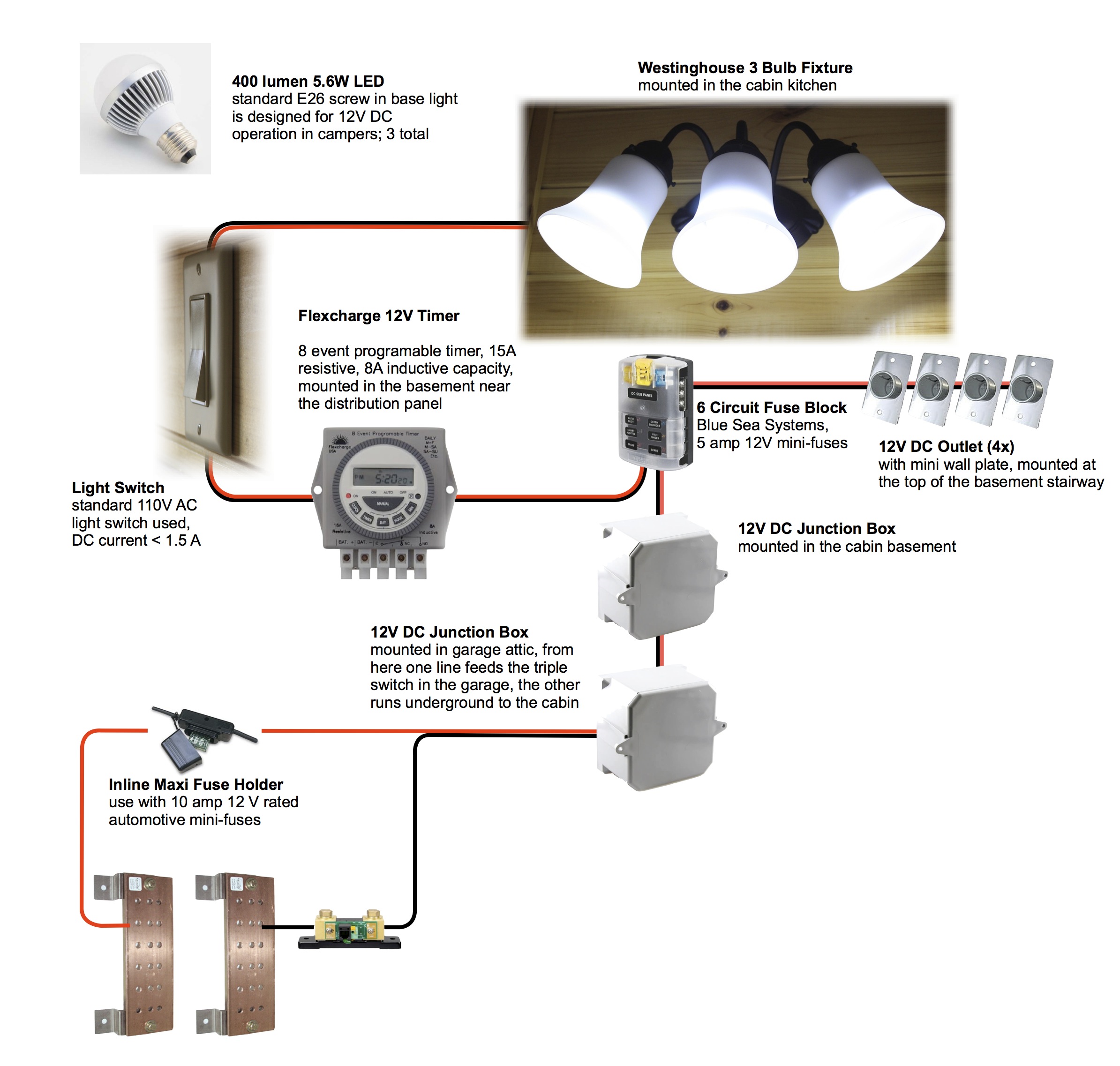
The wiring was a bit of a challenge and took about 3 hours to test and verify. I was sure glad I brought a multimeter to the cabin to test continuity or else I would have gone mad. The solid core ethernet cable could be stripped and inserted in to the five pin connector. The fit was good and once shrink tube was applied over the connection it produced a sound cable. I built several cables this way.

The 5-pin to ethernet adapter cables allowed the existing buried ethernet cable to be used for the new monitor. The original layout and design of the system allowed for these additions to be easily integrated.

The screen is intuitive and displays a lot of information at a glance. The bottom of the screen shows voltage, amps, watts. The time on the right side can mean one of two values depending on the battery icon: time to full charge or time until battery depleted. The battery icon has two small triangles that will point up if the batteries are being charged, or down if the battery is being under draw.

But wait! There is one more thing! Because the display shows all this information at a glance and we have wifi connected surveillance at the cabin, remote monitoring of the off grid system is now possible.

The camera holder simple and adjustable. It is just three elm boards drilled and threaded for 3/8″ rod with slots cut in two for adjustability. The boards are finished in shellac with self adhesive cork applied on the surfaces that contact the half wall.

Below is an image from the Blink camera. The camera is positioned at the correct distance for the auto exposure to adjust to the backlight and produce an easily readable image.

After a month of service it was decided the Renogy is here to stay. The temporary faceplate I made was discarded and the battery monitor was carefully hand fit into the wall.

off-grid system :: diagrams

CURRENT DIAGRAMS:

********************************

4.12.2014

  • off-grid inventory 5: (ADDED 4/12/2014) – I’m 18 months behind on this but I finally updated the inventory to include our conversion from CFL to LED lighting in the cabin. The update cost $486.10 for just 22 LED emitters. Wow how the price has changed. Non-the-less, we remain happy with the upgrade. LEDs in my observation offer much better lighting characteristics than CFLs and a wider choice of spectrum choices than incandescent.

********************************

8.26.2011

  • Cabin DC wiring 2 (ADDED 8/26/2011) – updated; now includes battery monitor
  • Cabin Power System Schematic 2 (ADDED 8/26/2011) – Completely reworked and updated! This is a huge improvement over the old schematic. And that big blank spot on the LED diagram – that is reserved for the technical drawings of the 12V LED install planned for the cabin. The wire has been run from the garage and the bulbs have been ordered. We’re going to use standard E26 screw in bulbs specifically designed for 12V DC with a wide 180° coverage with 400 lumen output at 5.6W – in other words: we can use a standard light fixture and wire it for 12V DC instead of 120V AC.

********************************

3.7.2011

Throughout the research and design phases of the project I created and updated this schematic: Cabin Power System Schematic (UPDATED 1/27/2011). Please note that the DC switches used in the LED light diagram are standard 110V AC light switches and not the toggle switches in the diagram.

  • Each item purchased in the construction of the system was also briefly catalogued in order to keep track of expenses: off-grid inventory 3 (UPDATED 7/31/2011). In this new inventory I’ve added pie graphs and itemized expenses by project.
  • I also created a DC wiring diagram (ADDED 3/7/2011) to better show how the panels, inverter, fuses, and breakers are connected.

I will continually update this post to reflect the current set up of the off-grid system.

Previews of the most recent documents (open PDFs above for easier viewing):

Overview Inventory

off-grid system :: settings

11.19.2012-Monday

Some fine-tuning has been going on. The battery monitor has been super accurate the past few weeks. I have marked the changes with an asterisk. The charge efficiency factor (CEF) has been adjusted and through trial and error 85% has been reached as the appropriate charger efficiency. This is after trying 74%, 80%, and 95% before arriving at 85%. Current threshold (Ith) was increased to cancel out noise from the 12V timer, garage sensor, and two outside LEDs – we need at least a 1.2A load to register anything other than zero current on the battery monitor. Only when the timer is “ON” and the kitchen lights are on will the current draw register on the battery monitor. Tail current (It) has been increased from 0.5% and should now be about 12A as cut off for charged (when charge current <12A and >13.5V has been achieved monitor registers batteries as “charged”). Charged detection time (Tcd) has been adjusted so the battery monitor more easily registers a charged battery bank as 100% full sooner. Time to go (Tdt) has also been lengthened to 1 minute to more conviently show time remaining to 50% at a one-minute average load. Battery capacity (Cd) has been adjusted for winter – the batteries are cold (25-40°F).

Victron BMV-600s

  • *85%-  CEF (charge efficiency factor)
  • *1.20A – Ith (current threshold)
  • 1.25 – PC (Peukert exponent)
  • 13.5V – Vc (charged voltage)
  • *850Ah – Cb (battery capacity)
  • 50% – DF (discharge floor)
  • *0.8% – It (tail current)
  • *4 min – Tcd (charged detection time)
  • *1 – Tdt (time to go)

3.9.2012 – Friday <PREVIOUS SET POINTS>

The off-grid system is now approaching the two year mark (sine the install date of the solar panels). With a second winter on the way out I’ve had a chance to learn some of the subtleties of our particular battery/inverter set up and have now arrived at a reasonably set list of device settings. A common question I’ve observed from those wanting to install their own system is, “what settings should I use for my charge controller?” From this many more device settings questions arise. The finer points of choosing device settings will rely on manufacturer specifications, particularly those from the battery manufacturer. With that in mind, here is a complete list of the settings I’m using:

 Xantrex C60

  • 13.8V – FLOAT (CHG)
  • 14.7V – BULK (CHG)

Xantrex MS3000

  •  20A – Power Share
  • 100% – Max Charge Rate
  • 10.5V – Lo DC Volt
  • FLA – Batt Type
  • 1540Ah – Batt Size
  • 85W – Sense Below
  • 8s – Sense Interval
  • 3 – # Chg Stages
  • 15.5V – Egz Volts
  • On – Force Charge
  • 85V – Lo AC Volt
  • 45Hz – Lo AC Freq
  • 135V – Hi AC Volt
  • 65Hz – Hi AC Freq

Victron BMV-600s

  • 74%-  CEF (charge efficiency factor)
  • 0.10A – Ith (current threshold)
  • 1.25 – PC (Peukert exponent)
  • 13.5V – Vc (charged voltage)
  • 1500Ah – Cb (battery capacity)
  • 50% – DF (discharge floor)
  • 0.5% – It (tail current)
  • 45 min – Tcd (charged detection time)
  • 0 – Tdt (time to go)

CEF (Victron BMV-600s) is a particularly tricky setting. I may return to this post and edit that value from time to time. So far I’ve only been able to determine that 90% is too high, 50% is too low, and 74% is my best guess at this time.

batteries :: top 10 list

5.17.2012 – Thursday

I like lists. They convey complex information in an organized fashion (when correctly constructed). I’ve been reading through some old posts on the blog and realized I have a lot of information spread out over roughly 50 posts. Since I usually write a post at a milestone moment or when I learn something really cool my thoughts can get a little scattered. That’s why I created the “Posts menu” at the right and listed posts categorically – I’ve even tried to keep some congruity in how I title them. In the spirit of organization I’ve going to attempt to summarize some of the information that I think is fundamental to proper battery management.

The focus of this post is on batteries, since this is pretty much the single item in a completed off-grid system that requires maintenance and attention. The solar panels may require an occasional cleaning but I would consider this out of the ordinary since rain does a pretty good job at cleaning off dust and other particulates. The inverter and wiring should perform without flaw if correctly installed. So… on to batteries and the top 10 things I’ve discovered through trial, error, research, and observation (with FLAs). It’s best to read the list in order.

  1. Charge Lag. I observed this phenomenon first hand on Jan 3, 2012 at 11:30am. After discharging the batteries to 53.5% (measured by specific gravity) a charge current of 102A was applied for ~72 minutes for a total of 123.3Ah of charger input. The batteries measured at 55.5% when they should have measured a theoretical 57.4%. The key to understanding charge lag is ‘equilibrium’ – it takes time for the SG* to become uniform throughout the battery. Also, note that the opposite effect will occur under heavy discharge (SG measurements will be falsely elevated for a short time after applying a heavy discharge current). Mixing the electrolyte with a bulb syringe specific gravity instrument will not correct a SG reading for charge lag.
  2. Temperature and Capacity. Everything moves slower in colder temperatures – all the way down to the molecular scale. Charge lag will become more pronounced because of this: slower molecular movement will slow the mixing of regions of high/low SG. The chemical reaction that transforms the stored chemical energy of a battery into electrical energy will slow down as well, and lead to a loss of functional battery capacity – at the cabin our 1540Ah summer capacity will drop to around 900Ah when its 25-30°F. An interesting thing to note is that if the batteries are used the temperature will rise (see #3).
  3. Internal Resistance. Just like mechanical friction (eg, rubbing cold hands together to generate heat) batteries have internal resistance – which also generates heat. If batteries were 100% efficient at converting chemical energy to electrical energy they would produce absolutely no heat (my laptop would also run cooler). This is also why battery chargers cannot operate at 100% efficiency: apply 10Ah to a battery and it may capture as little as 5Ah of that current and shed the remaining 5Ah as heat.
  4. Capacity will vary based on discharge current. Many factors will affect battery efficiency. Battery manufacturers acknowledge this and list discharge rates and use the following notation: C/4 = 4 hours to completely discharge a battery.  A typical 220Ah FLA (Trojan T-105) has a C/2 = 145Ah, C/5 = 185Ah, C/20 = 220Ah, C/100 = 250Ah. Notice how capacity decreases with faster discharge rate. This is best understood because of greater internal resistance under heavy load (more energy lost as heat).
  5. Charge Efficiency changes with SOC. A battery with SOC <84% will readily accept a charge, in fact, it will accept roughly 91% of the charge current (only 9% is lost as heat). But when SOC >90% charge efficiency falls dramatically to <50% (over half of the charge current is lost as heat). The best way to try and understand this concept is to imagine setting a mouse trap or a larger jaw trap. Setting each requires that a spring be put under tension – the tension gradually increases, requiring more effort, until the trap is set. Just the same, a battery requires incrementally more energy to overcome resistance, as it approaches full charge. This is why it is best NEVER to use a generator for absorption or float charging! – it is resource intensive with little return. ALWAYS absorb or float charge with a renewable like solar.
  6. Sulfation (crystallization of lead sulfate). This term describes a chemical reaction occurring inside the battery at the plates. Lead sulfate forms under normal use and is reversed when the battery is charged shortly after discharging. Lead sulfate crystalizes and becomes permanent if the batteries are left in an undercharged state for an extended period of time (1+ months). It is best never to let a battery fall below 30%. It is a better rule to remain above 50% if possible. Charge current is a topic of interest when determining if the ratio of PV to battery is appropriate, or if there is adequate current to mix the electrolyte, but it is of no concern when worrying about sulfation. A fully charged battery is fully charged regardless of how long it takes. Regarding battery desulfators – don’t waste your money. The people who design and market this product lack a fundamental understanding of how radio-frequencies interact with matter; this product is most certainly a scam.
  7. 10°C / 18°F Rule. For every 10°C increase above 25-30°C (18°F above 77-86°F) battery life shortens by a factor of two – sulfation rate doubles. The opposite can reasonably be assumed for colder temperatures. This is why in winter I’m not overly concerned about the battery bank hovering around 85-95% SOC. Sulfation at 32°F is occuring at roughly 1/2 of 1/2 of 1/2 that as at standard temperature (8 times slower). However, it is still important to have a battery near full charge as often as possible, especially in warm weather.
  8. Battery Monitors are awesome. If you have batteries, you should have a battery monitor. And when setting it, be conservative. On the Victron BMV-600s I initially set charge efficiency factor too high. Now I have it set at 74%. Strive for accuracy when setting it, but have a back-up method of assessing battery capacity. I created voltage/SOC charts as a way to double check the battery monitor. Writing down a specific point to recharge (as a back up) also works as a good double check. For example, at the cabin 11.9V, 300W AC load, 36°F battery temp. is about 60% SOC based on a specific gravity measurement.
  9. Don’t forget to water FLAs. With flooded lead acid batteries, maintenance is required to keep them in top form. I wouldn’t be surprised if good battery care effectively doubles the life-span of a battery bank. Use safe practices when maintaining batteries and follow manufacturer instructions on when to water and at what point in the charge cycle to add water. For most FLAs water is added after a full charge, unless plates are exposed prior to charging. I list my supplies and procedure for checking SG on the math :: SOC charts post. My preference is to then equalize after adding water to fully charged batteries – I do this once or twice each year.
  10. Take good notes and save useful information. I write everything down and keep several spreadsheets with data on the cabin system as well as every component manual and at least a dozen articles – all saved on my computer (and backed up). Keep a spreadsheet with key information on the battery bank. When recording information try and include date/time, specific gravity of each cell, voltage, current load (if applicable), and general observations/thoughts. It’s immensely helpful to have a baseline and provides a way to assess the performance over time.

I didn’t discuss battery equalization. There are many different approaches to this, from once a month to once a year. The rule of thumb is to perform this when SG differ by more than +/- .015 mg/ml between cells. Follow battery manufacturer instructions in this area.


*SG = specific gravity, SOC = state of charge; 0-100%

12V LED lights :: observations

5.13.2012 – Sunday

As readers of this blog will know, the cabin uses two electrical system that have a shared power supply.  Each system is connected at the buss bars over the battery bank. While the 3000W pure sine wave inverter is run occasionally (well pump, microwave, TV, lights and fans during the evening hours) the 12V system is on all the time. I am a fan of ‘form follows function’ and believe that the most eloquent designs are the simplest and most appealing to the eye. Take a look at the wall with the inverter and you’ll note how I’ve kept things as clean and organized as possible without compromising safety or function.

So then, with this atitude toward simplicity why all the trouble and fuss of adding two electrical systems – 12V and 110V? Well, both have their own set of advantages and disadvantages. 12V is low-power, super efficient for small electrical loads, but poor at transmitting significant power – especially over distances. 110V is great at running heavy loads, transmitting power over distances efficiently, but in order to have that power on demand a 50-70W phantom load (baseline) is required to keep all the electronics humming and ready to convert 12V DC to 110V AC – not too good a thing when running small loads for extended periods of time.

The solution I sought out was not to compromise, but have the best of both. This also meant a lot of extra work, higher overall cost, but greater efficiency, and expanded capability from our off-grid power system. The 12V system was initially conceived out of the goal of making the cabin and garage look ‘lived in’ or ‘used’ whether or not someone is presently at the cabin. This goal was achieved with the installation of several lights on the garage, the all-star from this install being the 12V motion light on the front of the garage. The garage was relatively easy to wire since the attic is completely open and easily accessible from an access panel in the ceiling. This was the initial foray into 12V DC wiring and lighting. The success of this first install and overall function was so favorable that I began drawing up plans to add 12V to the cabin.

For the cabin, the install was much more difficult. A junction box was added to the attic in the garage, tapping into the existing 12V wiring in the garage. From there the wire was run down the wall, then out the side of the garage, trenched underground between cabin and garage, and into the cabin basement to a corresponding junction box. And wiring in the cabin was still needed – this was only the step that brought 12V power to the cabin. A lot of trouble for a few lights. But this most recent 12V wiring install ended up providing a fused junction box with the capability to wire in six independently fused 12V lines in the cabin. Currently there are two lines wired in. The first is the kitchen LED light fixture on Flexcharge 12V timer. The second is a series of four automotive DC outlets that are part of a charging station at the top of the basement stairs. The timer, fused junction box, and automotive outlets are still technically ‘a work in progress’ so I haven’t posted on them yet. This winter we studded out the basement, insulated the walls, wired a dozen or more AC outlets and rewired a few light switches. On the agenda for this year is to panel the basement (pine paneling for the stairway, four different sizes of white-ash paneling for the basement, and rough cut for the firewood room). When things come together, and the 12V electrical components are permanently fixed to the wall, I’ll prepare a proper post with some pictures. For now here is an excerpt from an updated wiring diagram:

Image

Performance of 12V:

Running the LED lights straight off of the batteries has so far yielded no problems. With LEDs advancing as they have there have been no compromises (except for initial cost at the time of purchase). As far as lighting goes, nothing weird happens with flickering or dimming lights. The only odd behavior occurred when I plugged in a NiMH batter charger into the automotive outlet of the charging station. The pulse charging from the AA/AAA charger managed to flicker the kitchen lights. It was just enough to be noticeable. Suspect appliances like this could be direct wired to the battery with their own fused line, but at this time I don’t have enough ambition to wire in a separate line (even though there is a second line buried in case something like this happened). It’s easy enough just to charge batteries during the day or when we’re asleep. The long run from the batteries in the garage, up to the attic, down the wall, underground 30-40 feet to the cabin, and then 20 more feet to the fuse block using 14-3 trench log and 18 AWG track lighting wire + another 30 feet to the interior lights and outlets has not resulted in any performance issues other than the very specific AA/AAA charger/flickering issue. Also, using traditional 110V light switches has not been an issue either. As others have suggested, AC switches may not have the expected lifespan when used in a DC system if the DC voltage is >25% the rated AC voltage of the switch. So far I can attest to no issues when following this rule.

Lighting Characteristics of LEDs:

Before I start talking about lumens and the kelvin scale take a look at this graphic:Image

My preference is to use lighting near 3000K for general purposes. This ‘warm’ lighting is great for a comfortable cabin adorned with wood paneling and flooring. In the kitchen and the bathroom I prefer light near 5000K to 6500K. This quality of lighting is cool and similar to ‘work bench’ lights. 6500K is great for seeing fine details, dirt, putting contacts in, et cetera. When selecting an LED to purchase trust the kelvin scale – DO NOT TRUST photos comparing several different light bulbs. On my DSLR camera I can manually set white balance – which also relies on the kelvin scale. If I were selling LED bulbs and want to make my bulb look better than the competition I would manually adjust white balance to make the LED light color characteristics look superior than the competition. One last consideration with LEDs is spectrum of light. Take a look at this graphic I borrowed from Popular Mechanics:Image

The important detail to take away from spectrum is that not all light sources that produce ‘white light’ do so in the same way. Since light is a balance of several colors there are infinite combinations and intensities of each color of light that can produce ‘white light’. This is why a 2700K fluorescent bulb, 2700K LED, and 2700K incandescent bulb can all look different to the human eye – despite having the same kelvin rating. If you can first see a bulb in person – do it. If you can’t, then rely on reviews and look for a kelvin rating. And always look for a lumen rating to determine how much output a bulb has.

Final thoughts on LEDs at the cabin:

The LEDs on the garage have handled the elements quite well. The RAB light fixtures housing the LEDs have also held up very well (good thing considering the cost). These MR16 style 2-pint base LEDs and fixtures have a slightly bluish tinge. I wouldn’t want that for interior lighting but for exterior lights the blue tinge makes the LEDs appear brighter than the 330 lumen rating and reminds me of mercury vapor yard lights – only on a much smaller scale. Inside, the triple LED fixture in the kitchen shines with 400 lumen 6500K LEDs with the E26 style screw in base. These bulbs were relatively affordable at $22 each and designed for use in campers. A conservative estimate puts the light output of 400 lumen of LED equivalent to a 30W incandescent bulb. In order to consider replacing standard light bulbs with LEDs the output is going to need to be 800-900 lumen range. The most promising replacement bulb for 110V AC applications at the moment is made by Philips. That bulb is 940 lumen, 2700K, and 10W – impressive stats. I think ultimately this bulb and others like it will lead the way in replacing CFLs. But presently at $50 I think we’re still 3-5 years away from LEDs gaining significant market share. Time will tell.

batteries :: what I’ve learned

3.20.2012 – Tuesday

I wouldn’t say that I love to research a topic but I have a tendency to disconnect from reality for a time while I focus on finding the answer to a burning question or some topic of intense interest. After more time than I’d like to recount, I’ve collected my own notes on flooded lead acid batteries (FLAs) and compiled them into a spreadsheet. WordPress isn’t the friendliest when it comes to handling spreadsheets so I converted everything over to a JPG for the sake of preserving my formatting.

Here is the PDF version of my FLA notes (printer friendly).

batteries :: new SG / SOC charts

3.14.2012 – Wednesday

With time and experience comes knowledge… err, well, at least that is the hope. In my quest for knowledge I have revisited my old charts/graphs on state of charge (SOC) and specific gravity (SG). With new research and a more precise battery meter I took some time to update my charts. I determined that this was a worthwhile use of my time because of the unique set of conditions winter presents an off-grid system. The inability to reliably recharge the battery bank to 100% in winter added to the reduced capacity of cold batteries means that using the SOC readout of the battery meter is unreliable. SG is time consuming and not useful for daily monitoring of battery status. As a result, battery voltage, the old fallback, is the most useful measure of battery status.

My first task was to collect some data on batteries. I found some reference values for battery specific gravity and then extrapolated (most references list by 10% interval: 50%, 60%, 70%… so I used some simple math to make my chart list by 1% intervals: 50%, 51%, 52%, 53%, 54%…). After a bit more tweaking I ended up with a specific gravity chart that allows me to input the temperature (1st orange cell) and then auto-calculate the temperature-corrected SG from 10-100% at 1% intervals. This was step one. With specific gravity I can accurately find the SOC of the system. With that data in hand I can compare the current voltage on the battery monitor under specific conditions and prepare to make the next chart.

For chart number two I once again looked up reference values, this time for voltage, and then compared it with our system. It turns out that the open circuit voltage matched out system quite well. Under a load I could then measure voltage and compare to the true SOC (determined by SG). This next chart shows off my findings. I highlighted the reference temperature values (blue) and then created two input cells.

  • The green “input corrected V reading :: ” will correct for differences between reference values and actual system readings. Input one number, chart auto-calculates values
  • The red “corrected for 20 Amp load :: ” could be relabeled for any load. This input does the same as above but now makes the voltage readout more reliable under normal use (batteries under a load). I picked a normal system load for the cabin and used it (20 Amp) for this value.

Here is the PDF file of above as well as an excel version (with some additional graphs)

To sum it all up: we use SOC on the battery monitor in summer (system reaches 100% charge often, batteries are warm, functional capacity of the battery bank is known) and use voltage in winter (system rarely reaches 100% SOC and batteries have diminished capacity from the cold).

wild life :: birds

3.11.2012 – Sunday

Last time I wrote a post on wildlife it was a rare capture on the game camera of a pair of coyotes taking down a fawn. Before that in the post “battery enclosure I” there was a bobcat. While I’m still waiting for a picture of a wolf I was more than happy to get a few great captures this past week:

Gold Finch

Common Redpoll

White-Breasted Nuthatch

Grey Squirrel

Pine Grosbeak

Female Pine Grosbeak

Trumpeter Swan (largest swan in the world)

Bald Eagle

off-grid system :: efficiency

2.12.2012 – Sunday

I recently took a few minutes to plan a few posts for the next month or two; stuff that I’ve been working on for a while and feel should be on this blog because as anyone who has ventured into alternative energy will tell you, there is a lot of head scratching. So if you ended up at this blog because the way you understand reality doesn’t quite mesh with what your off-grid system is telling you, I might be able to help. So along those lines, there is something that probably gets overlooked quite often when designing an appropriate system for the electrical loads planned: efficiency.

“Derate to 70%” is the most common number/statement you’ll hear. If only it was that simple. While that might be the case for the mechanical bits in a system, nothing is ever simple when it comes to batteries. Battery charge efficiency is not a stable number. It changes depending on how charged up the battery is because of something known as internal resistance. Basically internal resistance increases as a battery nears a fully charged state, making the battery more resistant to accepting a charge. Here is an article from Sandia National Laboratory addressing this very issue: FLA study – charging efficiency

About a year ago I calculated the efficiency of our off-grid system… and a few days ago I adjusted those calculations to take the batteries into account. When taking a look a my numbers you might notice I am a bit optimistic about the efficiency of the panels. Most solar panels will be labeled “X” number of watts +/- “X”% so it’s not unlikely that in a PV array some panels will be capable of producing above the rated output and some will produce below. The panels at the cabin are rated 135W ± 5%.

If you would like to play with my numbers or use the spreadsheet as a template, here are a few more file formats. Since I have a Mac and prefer to use the iWork suite of apps, the Excel document was converted from a Numbers document so it will look different than the PDF.

PDF – System Efficiency

XLS – System Efficiency

brief update :: Ford TC33 tractor

1.21.2012 – Saturday

While my attempts to understand the electrochemistry of cold batteries are stalled until spring, when warmer temperatures will give me a true comparator, there is another mystery at the cabin: The Ford-New Holland TC33 compact tractor.

The sturdily built 33hp 3-cylinder diesel tractor suffers from one small defect… it doesn’t start. Well, sometimes it does. Sometimes it doesn’t. Less than ideal when it is relied upon for snow removal. While we love spending time at the cabin, we’d prefer not to get snowed in until the spring. The tractor has proved to be a valuable asset to our activities at the cabin, but lately the privilege of ownership has been less than pleasant. Recently some $1000 dollars was sunk into replacing a gear that engaged the PTO – it was never “properly adjusted from the manufacturer” and over time it was ground down into an impressive bit of malformed metal. Right now it resides on the workbench in the garage – I’ll have to snap a picture sometime. Oh, and this happened just a tad after the warranty was up. Nothing like paying extra money to fix something that was more or less broken on the day of purchase.

So that brings me to the issue at hand. The starter will not “go” when called upon to turn over the engine. The starter was replaced… twice, without fixing the problem. Fuses were inspected and one was cleaned up and replaced. Now a few relays are under investigation. It could just be one of the safety switches acting up – in order for the tractor to start you must, A) sit in the seat or have the brake engaged, B) have the PTO off, C) have the tractor in neutral. We’ll see… maybe.

When functional it’s a great tractor. For now it seems to be working alright. It’s all back together and fully functional – though it sounds like the Ol’ man managed to strip a bolt somewhere under the hood, in such a manner that it can’t be easily fixed, while in the process of attempting to check the relies/fuses.  I guess the bolt threads through some plastic and holds the lid on a fusebox or some-such.

Overall, things are well at the off grid cabin. My wife and I recently spent some time at the cabin and visited Marquette for a day. The Ol’ man and mother have been spending some time at the place, and it sounds like this winter might be the winter someone finally has a successful coyote hunt.